Image forming apparatus, process unit, and developing cartridge

a technology of image forming apparatus and developing cartridge, which is applied in the direction of electrographic process apparatus, corona discharge, instruments, etc., can solve the problems of affecting the printing paper transport pathway space composed of the processing cartridge and the body of increasing the displacement of the processing cartridge relative to the image formation device, and affecting the printing of paper. the effect of paper handling and/or other benefits

Inactive Publication Date: 2007-03-01
BROTHER KOGYO KK
View PDF12 Cites 13 Cited by
  • Summary
  • Abstract
  • Description
  • Claims
  • Application Information

AI Technical Summary

Benefits of technology

[0011] Aspects of the present invention address one or more issues desc...

Problems solved by technology

Therefore, the possibility has existed that the amount of displacement of the processing cartridge relative to the image formation device would increase, or in other words, that positioning precision of the processing cartridge relative to the image formation device would worsen.
Also, as the positioning precision of the processing cartridge relative to the...

Method used


Image

  • Image forming apparatus, process unit, and developing cartridge
  • Image forming apparatus, process unit, and developing cartridge
  • Image forming apparatus, process unit, and developing cartridge

Examples


embodiment 1

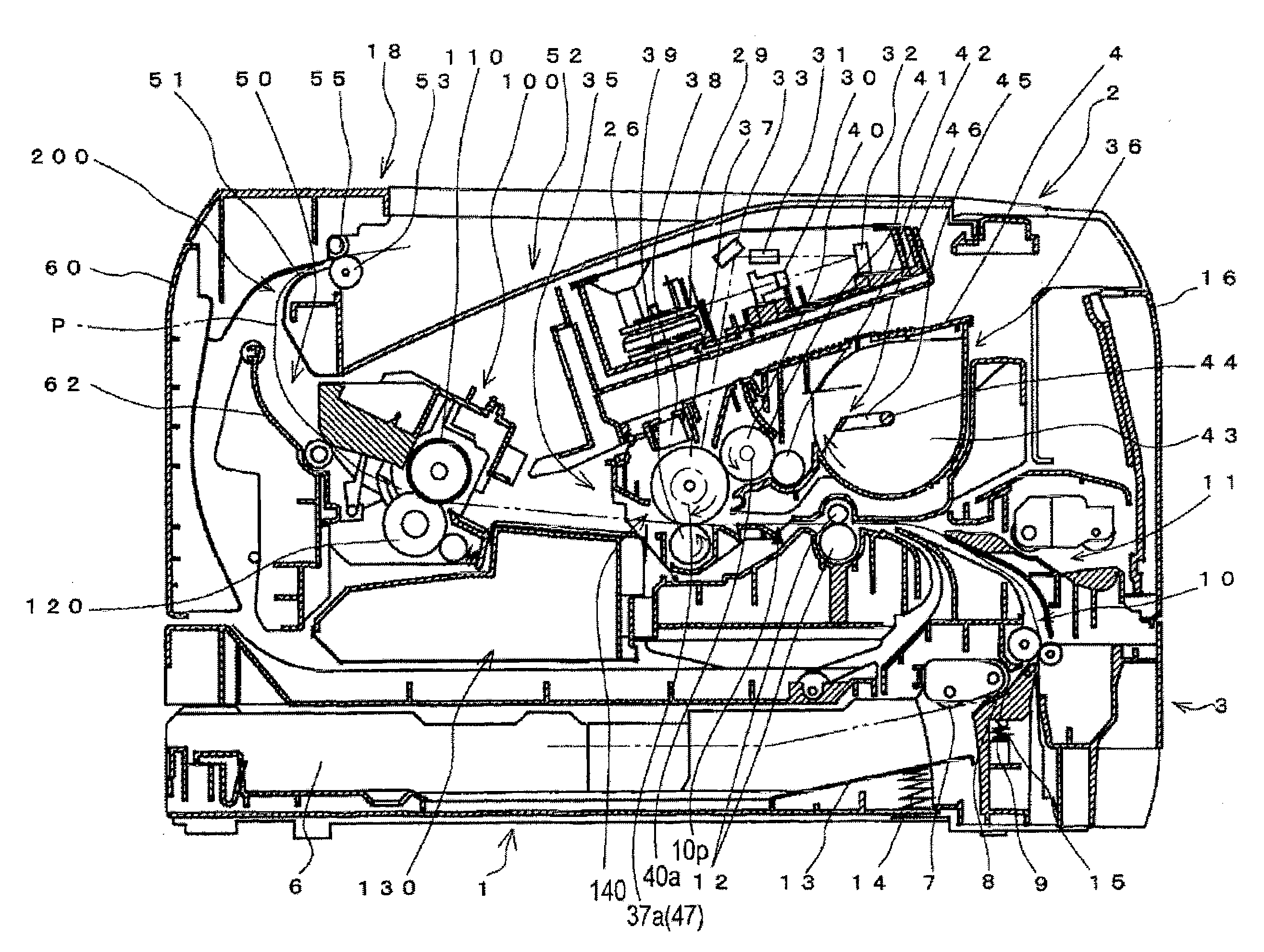
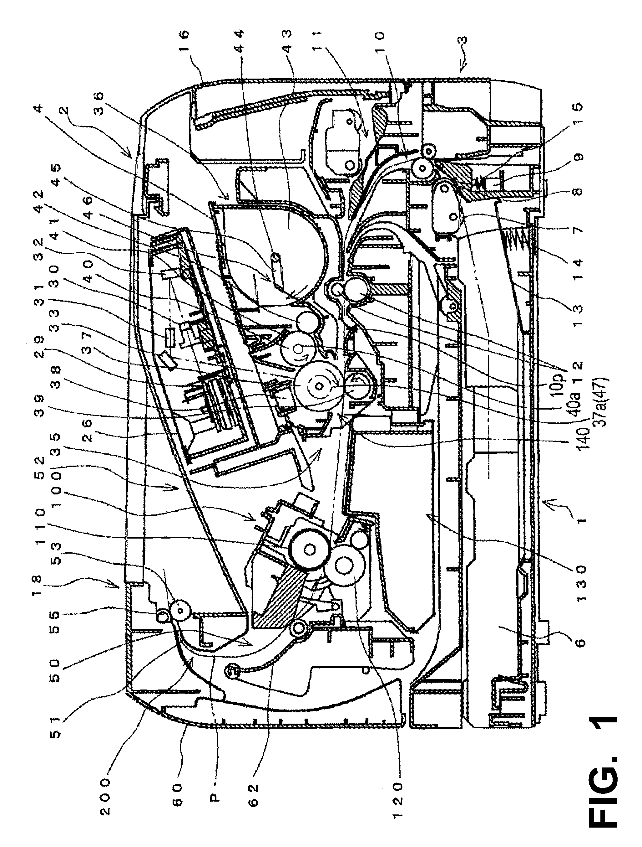
[0027]FIG. 1 is a schematic sectional side view of a laser printer 1, which is used to illustrate one example of an image forming apparatus according to the present invention.

[0028] As shown in FIG. 1, the example laser printer 1 includes: a paper feed 3 for the purpose of feeding paper P, a process unit 4 that operates as an image forming component (e.g., forms a developer image that is a visible image on the paper P that is fed), a fixing unit 100 that fixes the developer image that has been formed on the paper P, and a paper eject 200 that ejects the paper P that has passed through the fixing unit 100, etc. These systems are provided within a body casing 2 that includes a top cover 18, a front cover 16, and a rear cover 60, etc. Furthermore, in the present example printer structure 1, the rear cover 60 is considered to be the “rear” and the front cover 16 is considered to be the “front.”

[0029] The paper feed 3 is equipped with a paper cassette 6, feed rollers 7 and 8 (which are ...

embodiment 2

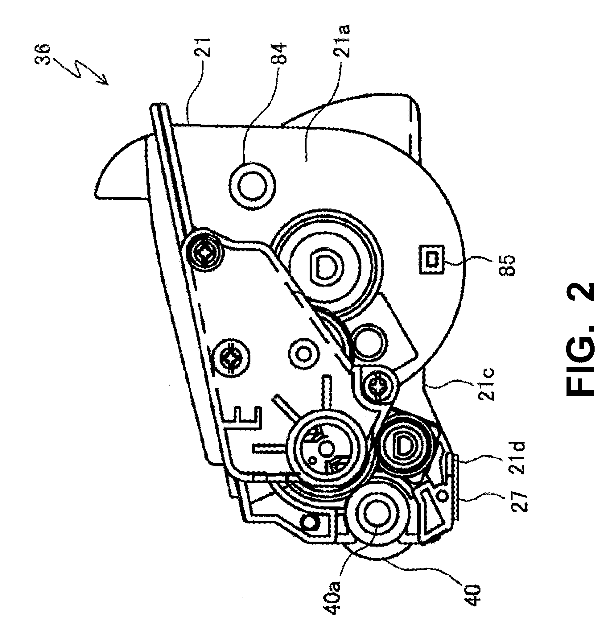
[0066] Next, a laser printer 1 of a second example embodiment according to this invention shall be explained using FIGS. 7 and 8.

[0067] As shown in FIGS. 7 and 8, with the laser printer 1 in this example embodiment, the positioning component 84 of the developing cartridge 36 that engages with the developing cartridge engagement 22 of the laser printer 1 is configured so that it also engages with the rotation inhibiting element 76 of the photosensitive drum cartridge 35. Therefore, because the positioning component 84 engages with the developing cartridge engagement 22, the developing cartridge 36 is positioned so that it cannot move relative to the laser printer 1. Also, because the rotation inhibiting element 76 of the photosensitive drum cartridge 35 is engaged with the positioning component 84, the photosensitive drum cartridge 35 is positioned so that it cannot move relative to the laser printer 1. Furthermore, in this second example embodiment, the shape of the rotation inhibi...


PUM


Abstract

When the drum axis of a photosensitive drum cartridge is engaged with an image forming apparatus, the developing roller axis of a developing cartridge is engaged with an engagement provided in the photosensitive drum cartridge. Then, after this, a positioning component of the developing cartridge engages with a developing cartridge engagement structure of the image forming apparatus, and the developing cartridge is thus positioned relative to the image forming apparatus. In addition, because an inhibiting device of the photosensitive drum cartridge and an inhibiting protrusion component of the developing cartridge are engaged, the photosensitive drum cartridge is positioned in the image forming apparatus via the developing cartridge. Because the developing cartridge may be positioned in the image forming apparatus without involving the photosensitive drum cartridge, the paper transport pathway space that is formed by the developing cartridge and the image forming apparatus is less likely to become disrupted.

Description

RELATED APPLICATION INFORMATION [0001] This application claims priority to Japanese Patent Application No. 2005-246109, filed Aug. 26, 2005, whose contents are expressly incorporated herein by reference. BACKGROUND [0002] 1. Technical Field [0003] The present invention relates to an electrostatic image forming apparatus and a process unit and a developing cartridge used for the image forming apparatus, e.g., in a copier, facsimile, laser printer, or other image forming apparatus. [0004] 2. Related Art [0005] Conventionally, in image formation devices that supply developer to an electrostatic latent image formed on a photoreceptor and record the visible image showing the characters or images formed by transferring them onto a recording medium, processing units of the cartridge type are well known, in order to improve and simplify the maintenance characteristics and the changing operation. [0006] With this sort of conventional image formation device, processing cartridges equipped wit...

Claims


Application Information

Patent Timeline
IPC IPC(8): G03G21/18
CPCG03G21/1821G03G2221/1884G03G2221/1861
Inventor KAMIMURA, NAOYA
Owner BROTHER KOGYO KK
Why Eureka
Try Eureka