Connector

a technology of connecting rods and connectors, applied in the direction of coupling device details, coupling device connections, electric discharge lamps, etc., can solve the problems of difficult downsizing of usb connectors, and achieve the effect of simplifying the mounting process of the receptacl

Active Publication Date: 2007-03-01
MATSUSHITA ELECTRIC WORKS LTD
View PDF4 Cites 58 Cited by
  • Summary
  • Abstract
  • Description
  • Claims
  • Application Information

AI Technical Summary

Benefits of technology

[0022] According to the configuration described above, when the receptacle is mounted on the printed wiring board, the terminal part of the first posts does not overlap with the terminal parts of the sec...

Problems solved by technology

However, with recent trend toward compactness of the peripheral device, such a B connector having a relatively large size has difficulties in coping with the trend, so that a specification for a mini-B connector down...

Method used


Image

  • Connector
  • Connector
  • Connector

Examples


first embodiment

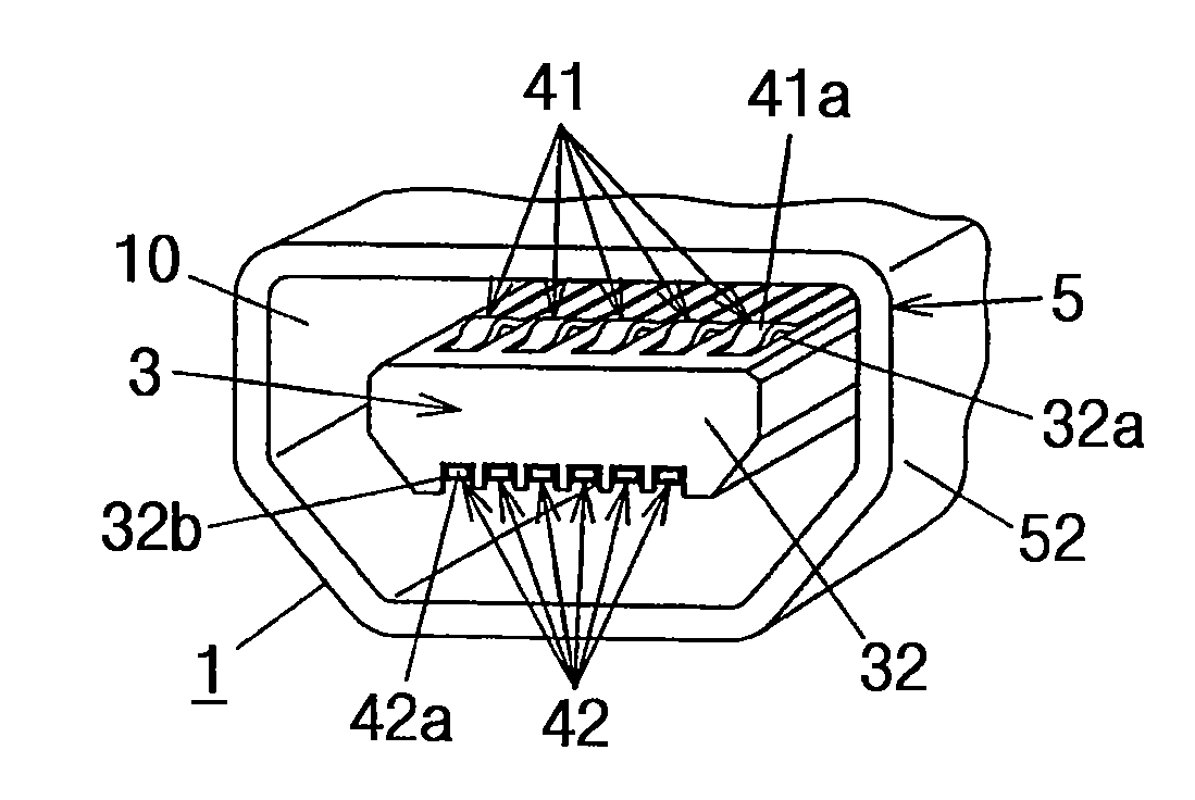
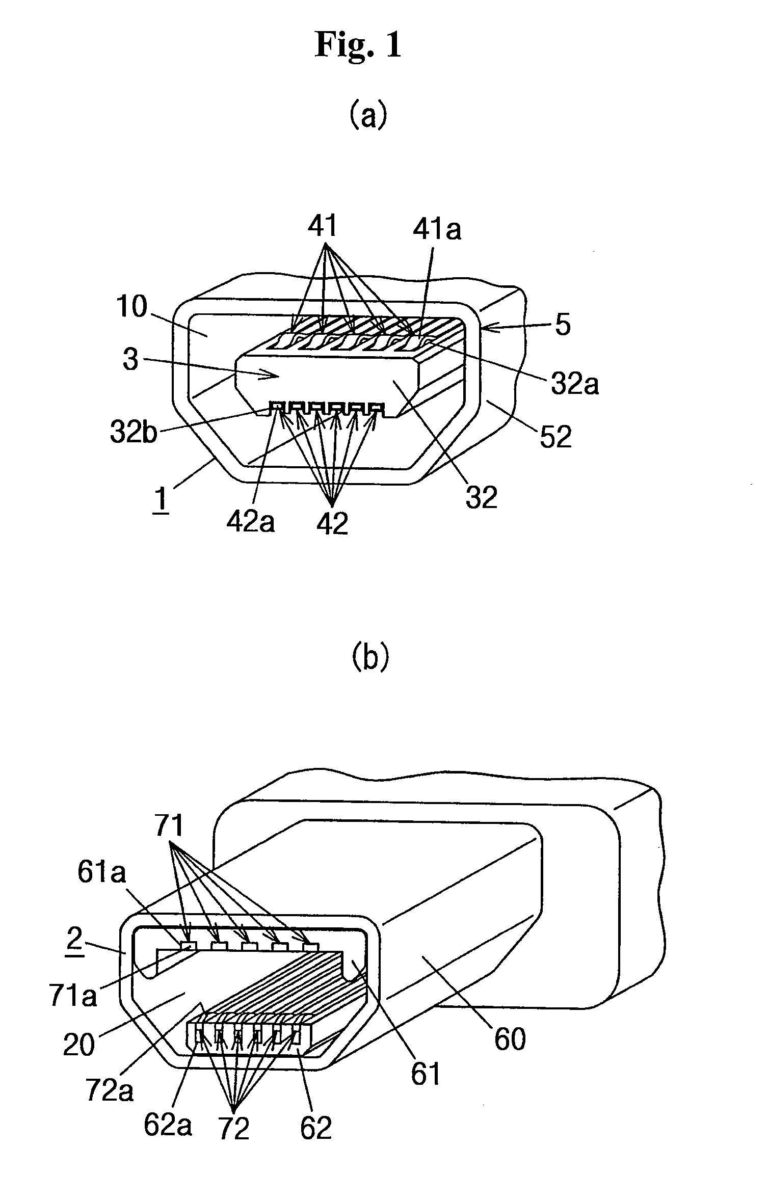
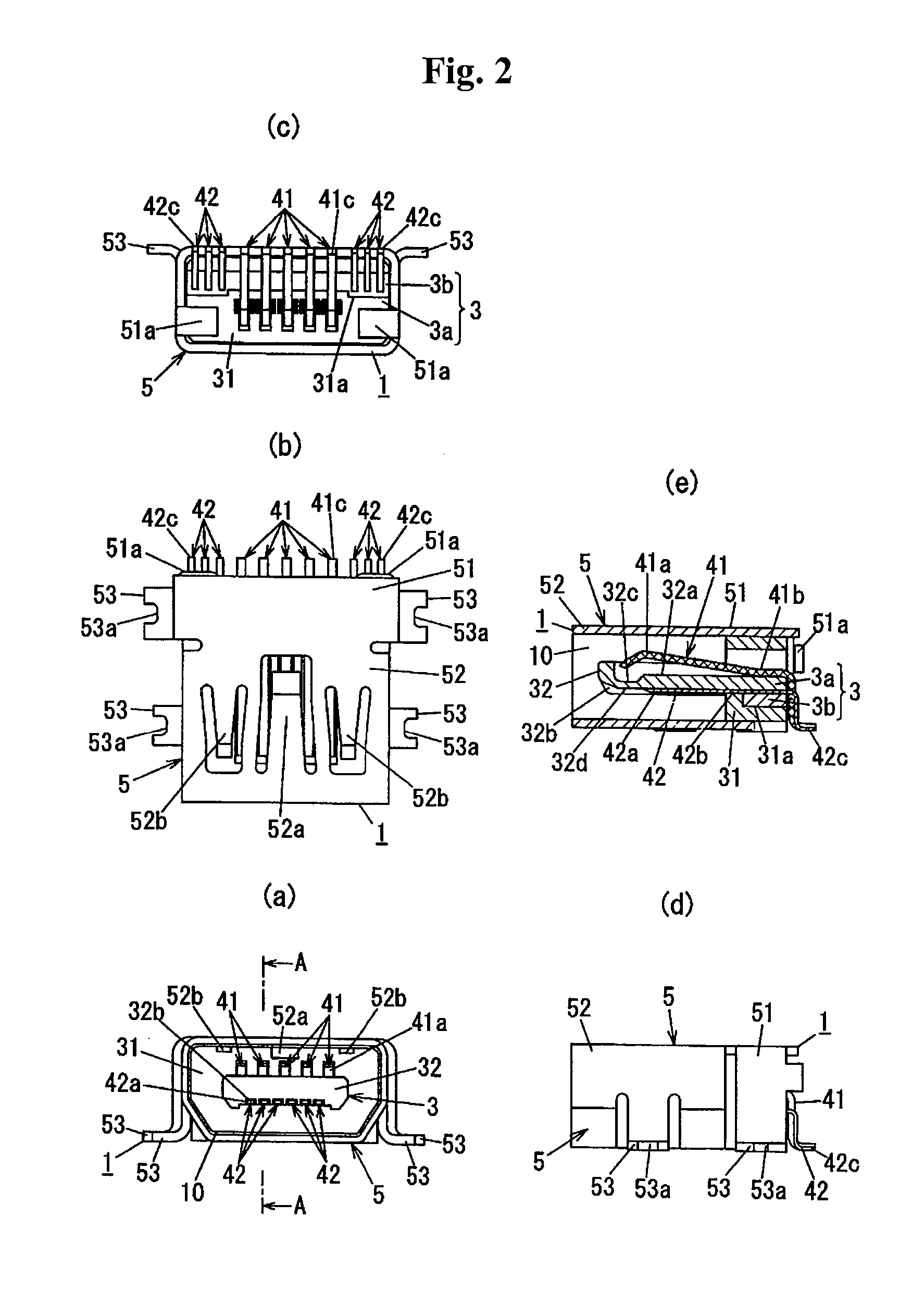
[0033] A connector according to a first embodiment of the present invention includes: a receptacle, as shown in FIG. 1(a), having second posts 42 in addition to first posts 41 similar to the mini-AB receptacle based on the existing USB On-The-Go (OTG) standard; and a plug 2, as shown in FIG. 1(b), having first contacts 71 corresponding to the first posts 41 and second contacts 72 corresponding to the second posts 42. The receptacle 1 is, for example, mounted on a printed wiring board (not shown) formed on a peripheral device, and the plug 2 is, for example, built on a front end of a cable (not shown). In the following description, the left, right, top, and bottom directions are defined by the direction in FIG. 1(a), that is, a direction extending from bottom-left to top-right in FIG. 1(a) is referred to a forward direction, and a direction extending from top-right to bottom-left in FIG. 1(b) is referred to as a backward direction. In addition, a mini-A (or mini-B or mini-AB) plug (o...

second embodiment

[0048] A basic structure of the second embodiment is similar to that of the first embodiment and like reference numerals in the drawings denote like elements.

[0049] As shown in FIGS. 7(s) and 7(b), the dimensions of the receptacle 1 and the plug 2 according to the second embodiment are different from those of the first embodiment.

[0050] In the first embodiment, it is made impossible to insert the plug 2 into the mini-AB receptacle by making the distance between the first contact retainer 61 and the second contact retainer 62 smaller than the depth of the connecting part (not shown) of the mini-AB receptacle. To the contrary, in the second embodiment, it is made impossible to insert the plug 2 into the mini-AB receptacle by making the height of the plug shell 60 greater than the height of the fitting recess (not shown) of the mini-AB receptacle. In the second embodiment, the plug shell 60 corresponds to a blocking part according to claims of the present invention. In addition, in o...


PUM


Abstract

There is provided a connector which can downsize the peripheral device. A receptacle 1 is capable of receiving both a mini-A plug based on a USB OTG standard and a mini-B plug based on a USB 2.0 standard. Further, the receptacle 1 includes first posts 41 compliant with the USB standard and second posts 42 disposed at an opposite side to the first posts 41 with a connecting part 32 inserted into a connecting recess 20 of a plug 2 therebetween. Furthermore, the plug 2 includes second contacts 72 corresponding to the second posts 42 in addition to first contacts 71 corresponding to the first posts 41. Accordingly, it is possible to transmit data other than the data which are transmitted through the known USB connector by using the second posts 42 and the second contacts 72. In addition, it is possible to down size the peripheral device compared to the case where the size increases when a connector for transmitting the other data is installed in addition to the USB connector.

Description

BACKGROUND [0001] 1. Technical Field [0002] The present invention relates to a connector capable of connecting a plug based upon a universal serial bus (USB) standard to a receptacle. [0003] 2. Related Art [0004] The USB standard has been widely adopted in a cable or a connector used for connecting a host device such as a personal computer to a peripheral device such as a digital camera. [0005] In the USB standard, specifications for an A connector connected to the host device side and a B connector connected to the peripheral device side are already established. However, with recent trend toward compactness of the peripheral device, such a B connector having a relatively large size has difficulties in coping with the trend, so that a specification for a mini-B connector downsized from the B connector based on a USB 2.0 standard is established, and a connector based on the specification is provided (for example, see Patent Document 1). In addition, there have been rising demands for...

Claims


Application Information

Patent Timeline
IPC IPC(8): H01R9/03
CPCH01R9/03H01R13/6456H01R13/65802H01R12/716H01R12/714H01R2107/00H01R24/60H01R27/00H01R13/6582H01R12/70H01R24/62
Inventor FUJIMOTO, MASAKIONO, HISAHIRO
Owner MATSUSHITA ELECTRIC WORKS LTD
Why Eureka
Try Eureka