

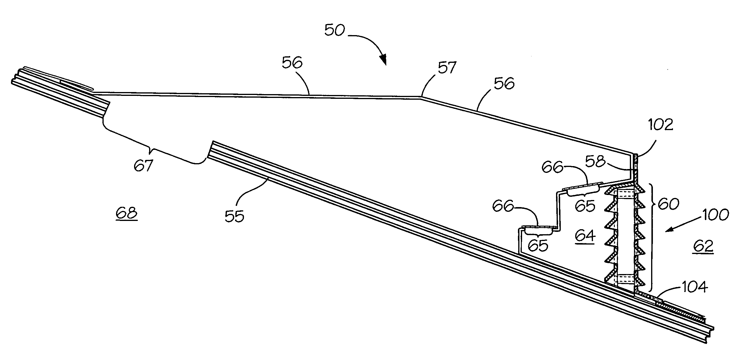
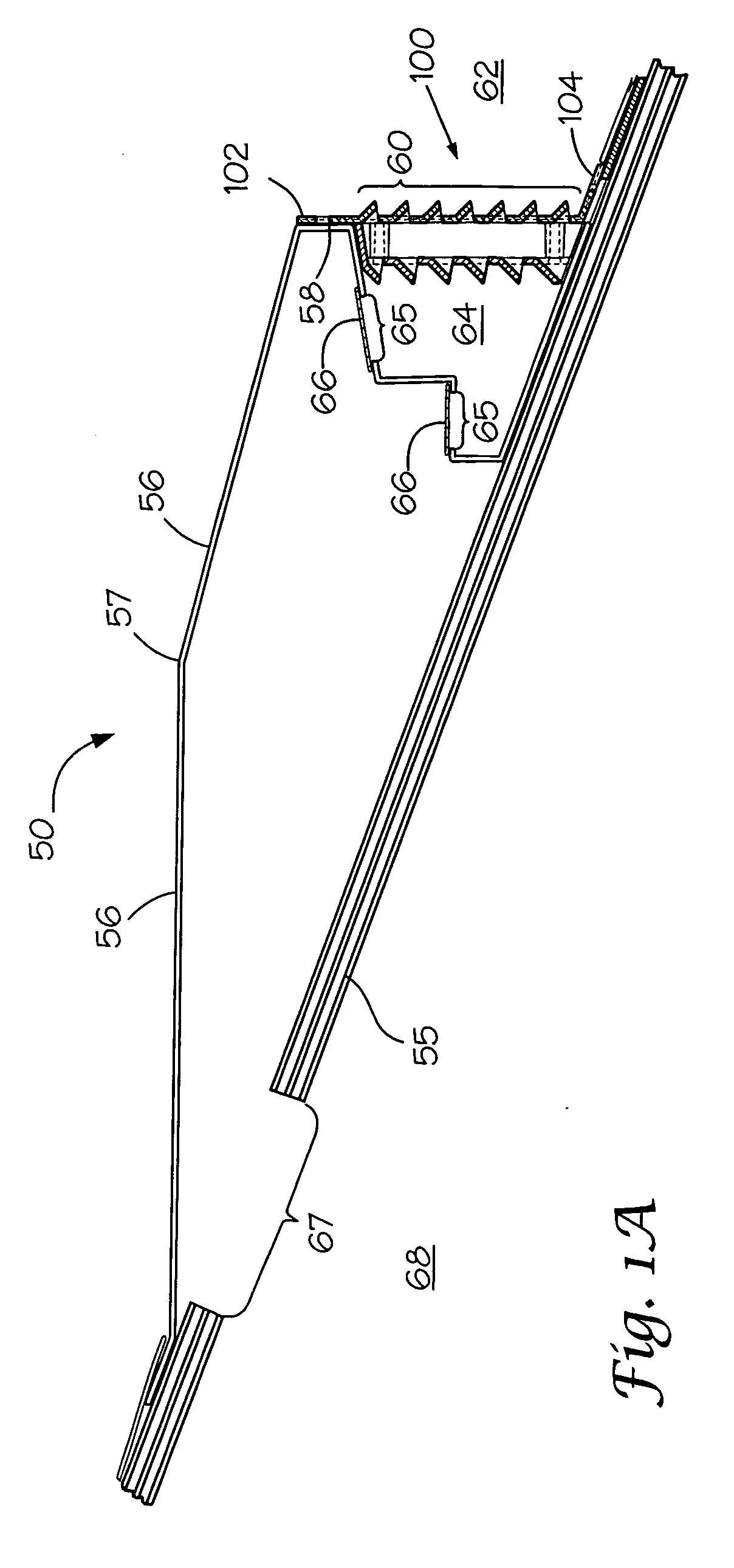
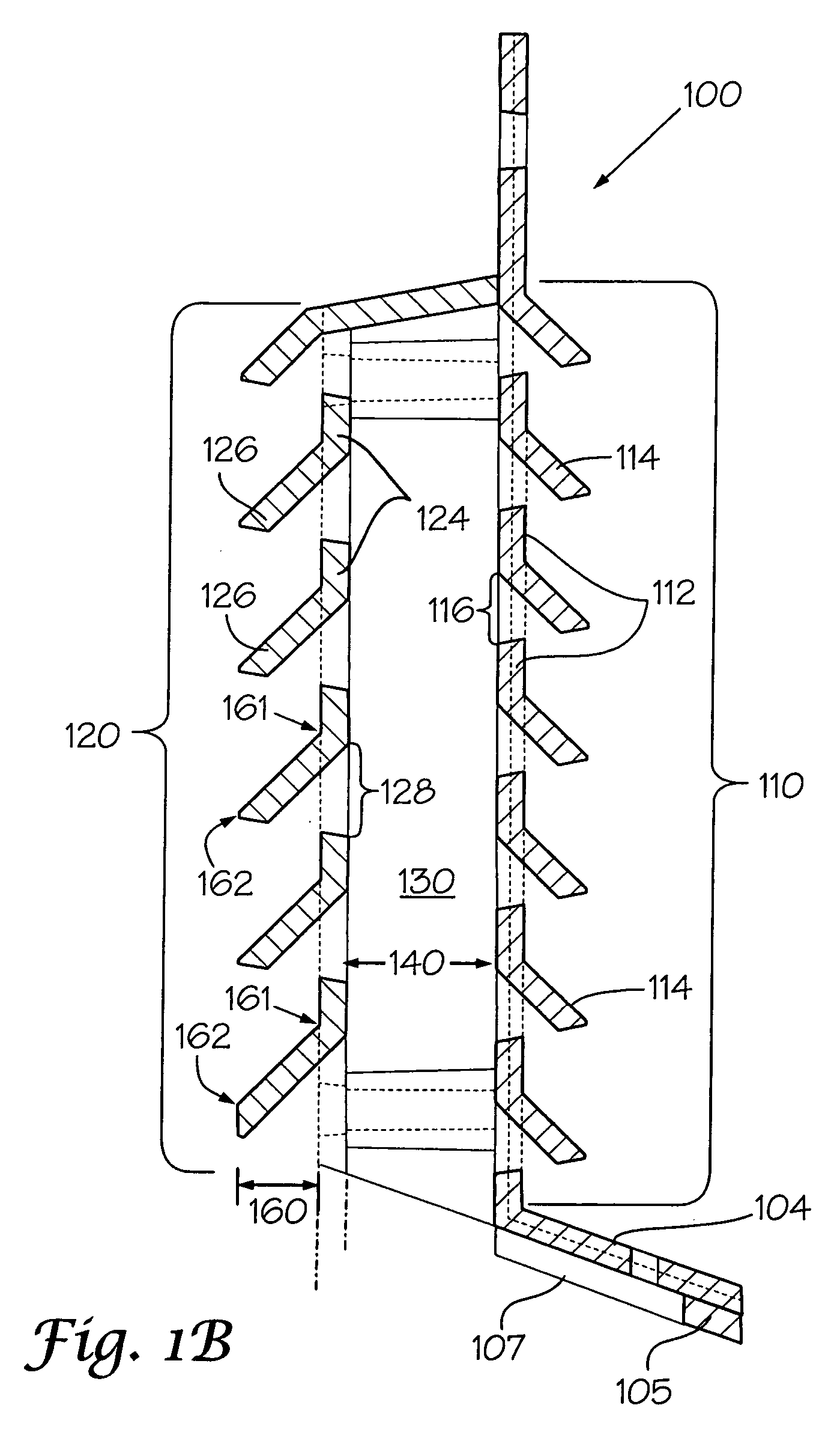
Ventilating moisture barrier for roof vent
- Summary
- Abstract
- Description
- Claims
- Application Information
AI Technical Summary
Problems solved by technology
Method used
Image

Examples
example 1
[0028] One approach to fabrication and assembly is exemplified in FIGS. 3A-C, 4A-C, and 5A. These are not meant to be limiting.
[0029] FIGS. 3A-C provide, respectively, front, transverse section, and cross-sectional side views of one embodiment of a first orifice plate panel 300 of the present invention, for assembly with a second orifice plate panel 400 as depicted in FIGS. 4A-C. Viewable in FIG. 3A are a structural body 302 and six sections 304 of louvers 306 that extend transversely (i.e., from left to right) and extend above like-disposed passages 307 (see FIG. 3C). The structural body 302 further is comprised of end sections 308, transverse ribs 310 between adjacent louvers 306 of a respective section 304, and vertically arranged structural major members 312 and lesser members 314 separating adjacent sections 304. It is noted that the end sections 308 at opposite left and right ends are molded offset to one another so as to provide a lap-type joining when a left side of one pan...
PUM
 Abstract
Description
Claims
Application Information