Method for kinetic (inertial) torque transmission and devices implementing it

a technology of kinetic torque and transmission method, applied in the direction of gearing control, gearing elements, gearing, etc., can solve the problem of effort to represent an engineered device capable, and achieve the effect of increasing fuel efficiency

Inactive Publication Date: 2007-03-01
KOLEV PETRE NIKOLOV
View PDF0 Cites 8 Cited by
  • Summary
  • Abstract
  • Description
  • Claims
  • Application Information

AI Technical Summary

Benefits of technology

[0019] (g) It is suitable for both small and big applications because of its simplicity and efficiency.
[0020] (h) It may be used in helicopters to increase fuel efficiency, because it would allow use of internal combustion engine without a heavy conventional transmission.

Problems solved by technology

The drawings are not an effort to represent an engineered device capable to withstand the forces resulting from their action.

Method used


Image

  • Method for kinetic (inertial) torque transmission and devices implementing it
  • Method for kinetic (inertial) torque transmission and devices implementing it
  • Method for kinetic (inertial) torque transmission and devices implementing it

Examples


embodiment

Preferred Embodiment

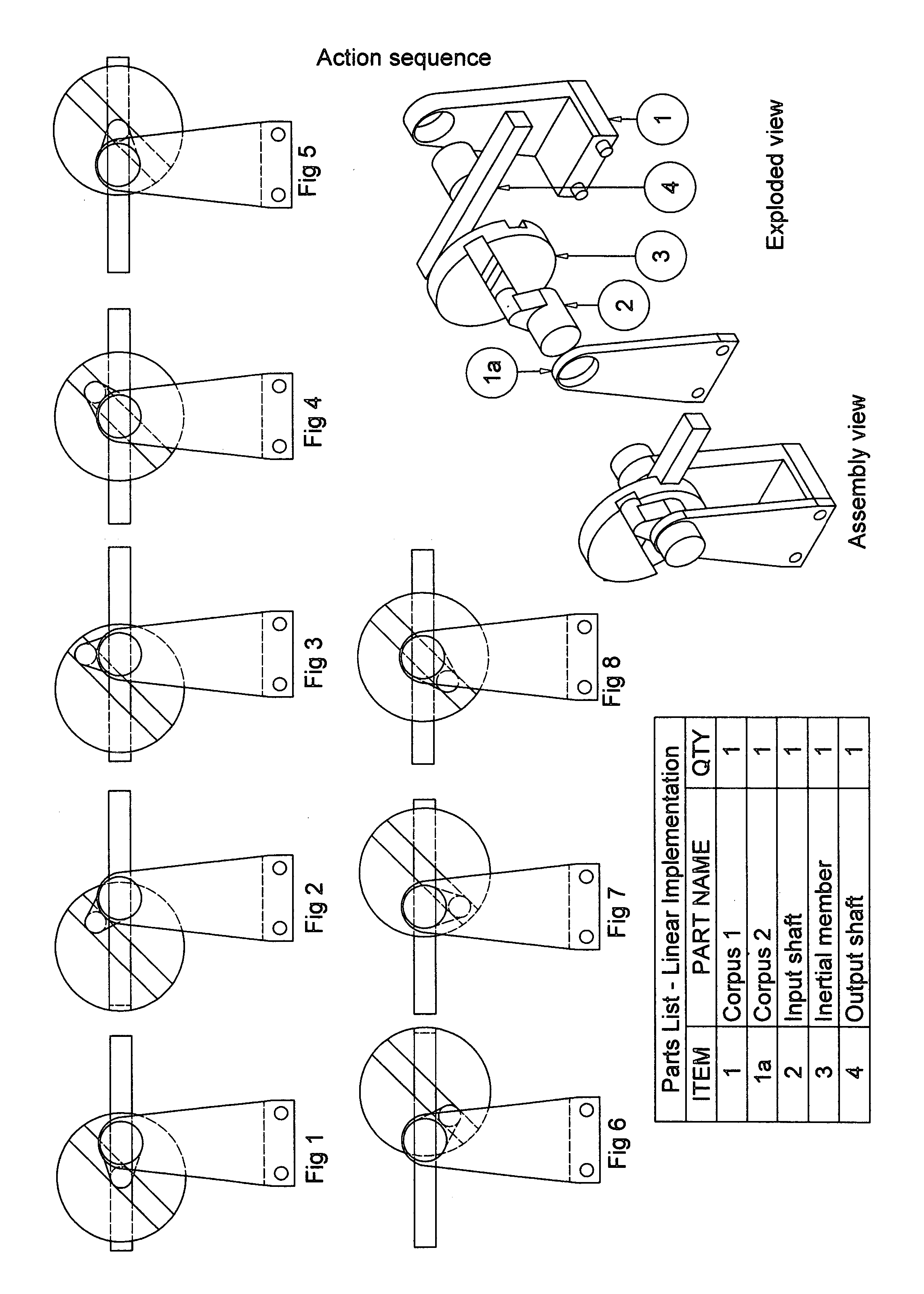
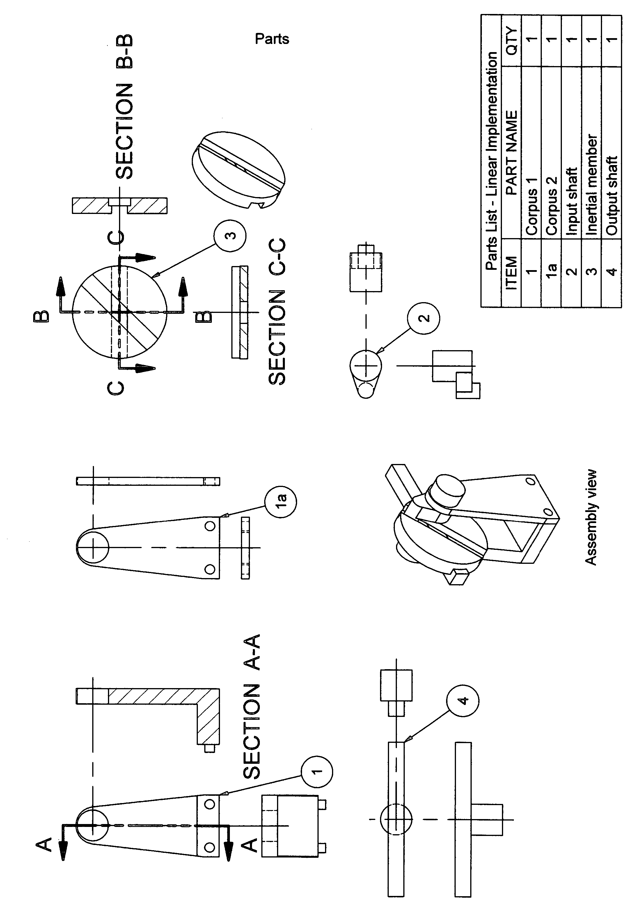
[0048] Inertial Tourque Converter—Linear Implementation

[0049] This simplified linear device consists of four main elements as follows:

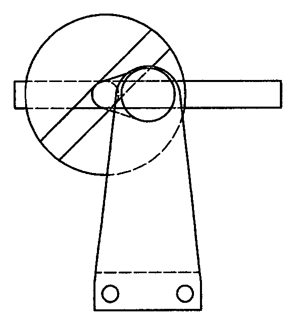
[0050] Corpus 1 and la comprise the main support element. The corpus 1 has a hole into which the cylindrical end of the output shaft 4 is inserted providing only rotational freedom for it.

[0051] Output shaft 4 also has a straight wedge, which is inserted into one of the two slots milled in the two flat surfaces of the inertial member 3. It provides the inertial member with freedom to only move along that wedge. Inertial member inherits rotational freedom from the output shaft. Inertial member 4 has a shape of a cylindrical disk with two slots, one on each of the flat sides milled at an angle related to each other that can vary in order to deliver different performance characteristics, but here for simplicity is 45°. This angle is one of the factors that determine the amount of displacement of the inertial member 4 during the cyc...


PUM


Abstract

A method for transmission of rotational or linear energy and a device implementing that method in which inertia of a member that is a non liquid physical body put in motion repeatedly by a difference in the angular or linear speeds of an input shaft and an output shaft is the means for providing variable degree of engagement between said shafts where the number of changes in speed or speed and direction of said member and therefore said degree of engagement is proportional to the difference of linear, angular or linear and angular speeds of said input and output shafts. Since the degree of engagement greatly depends on the mass of the inertial member changing the mass of said member during operation can further expand the range of torque transmitted.

Description

CROSS REFERENCE TO RELATED APPLICATIONS [0001] Not Applicable. FEDERALLY SPONSORED RESEARCH [0002] Not Applicable. SEQUENCE LISTING OR PROGRAM [0003] Not Applicable. BACKGROUND OF THE INVENTION [0004] 1. Field of Invention [0005] This invention relates to a method for power transmission of torque from a power source, such as combustion engine to a load, such as the driving wheels of a car, truck, motorcycle or any other device that utilizes the use of torque. [0006] 2. Background of the Invention [0007] Most mechanical transmissions function as rotary speed changers; the ratio of the output speed to the input speed may be constant (as in a gearbox) or variable. On variable-speed transmissions the speeds may be variable in discrete steps (as on an automobile or some machine-tool drives) or they may be continuously variable within a range. Step-variable transmissions, with some slip, usually employ either gears or chains and provide fixed speed ratios with no slip; step-less transmiss...

Claims


Application Information

Patent Timeline
Patent Type & Authority Applications(United States)
IPC IPC(8): B60W10/02F16H61/14
CPCF16H21/14Y10T477/78Y10T477/735
Inventor KOLEV, PETRE NIKOLOV
Owner KOLEV PETRE NIKOLOV
Why Eureka
Try Eureka