Rod to rod connector

Inactive Publication Date: 2007-03-01
AESCULAP AG
View PDF98 Cites 156 Cited by
  • Summary
  • Abstract
  • Description
  • Claims
  • Application Information

AI Technical Summary

Benefits of technology

[0021] In a preferred embodiment, the first clamp of each pair further comprises a plurality of flanges defining a collar that extends coaxially from the screw hole, which flanges fit within the screw hole of the second clamping body when the two clamping bodies are aligned and joined. The flanges spread outwardly when forced downwardly by a screw h

Problems solved by technology

This is more severe in cases where the set screw tip is conically shaped such as that found in FIG. 6 of the Drummond et al. patent.
This causes deeper, more localized deformation and therefore stress inducing indentation that can lower rod fatigue life.
Most of these systems present one or more difficulties for spinal surgeons.
Many of the devices are high profile, which increases soft tissue tr

Method used


Image

  • Rod to rod connector
  • Rod to rod connector
  • Rod to rod connector

Examples


Embodiment Construction

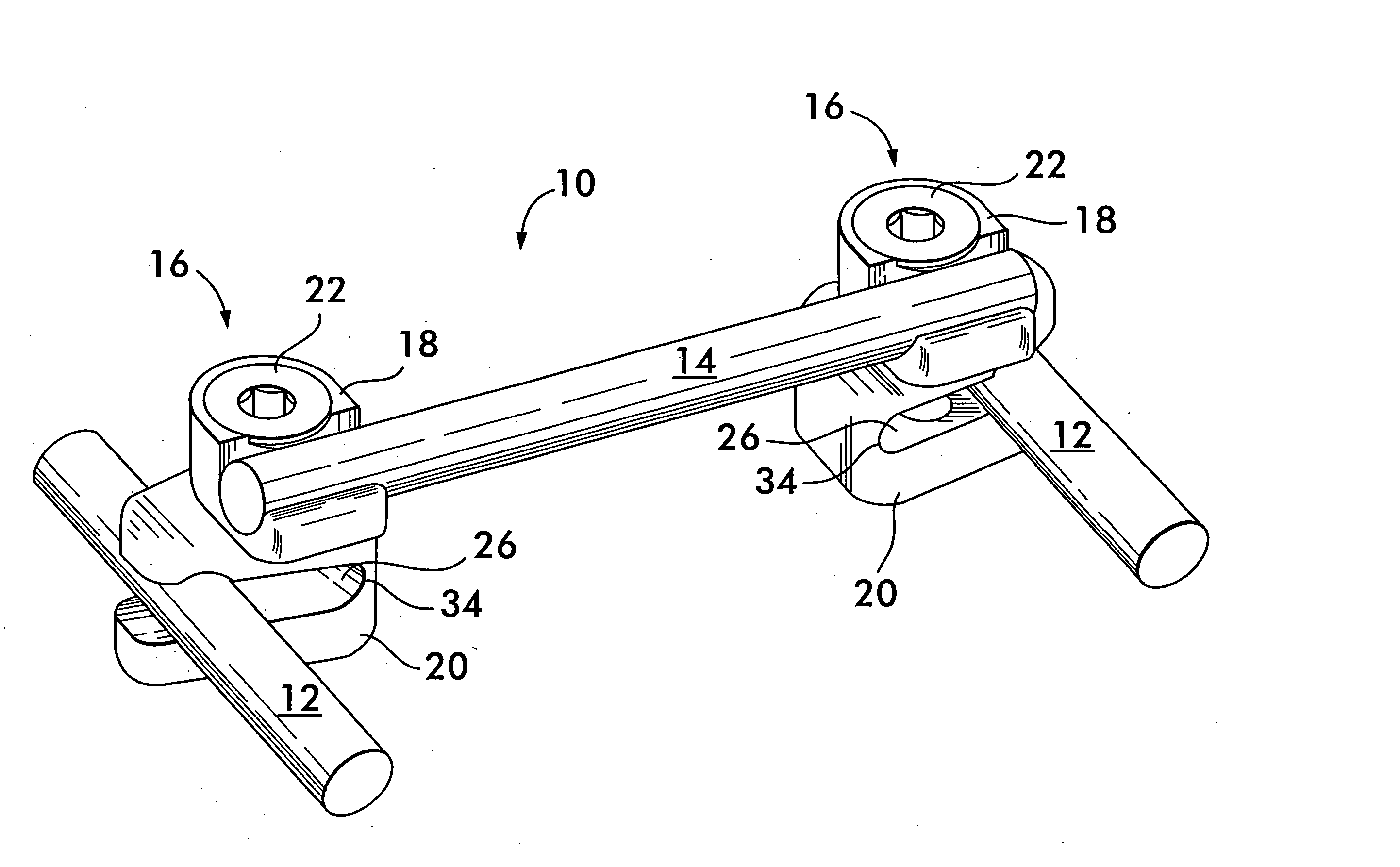
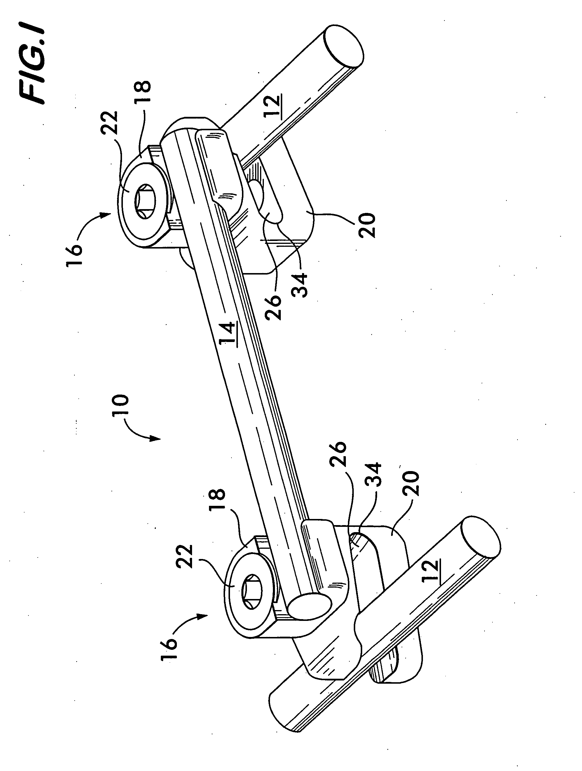
[0035]FIG. 1 is a perspective view of a rod to rod connector 10 in accordance with the present invention interconnecting two generally parallel spinal rods 12. The connector 10 comprises a transverse rod 14 and a pair of clamping assemblies 16. Each clamping assembly 16 comprises an upper clamping member 18 and a lower clamping member 20. Preferably, to two upper clamping members 18 are identical to each other and the two lower clamping members 20 are identical to each other. Each clamping assembly 16 further comprises a screw 22. The clamping members 18 and 20 preferably are made of a biocompatible, resilient material such as titanium, stainless steel, or any number of biocompatible polymers.

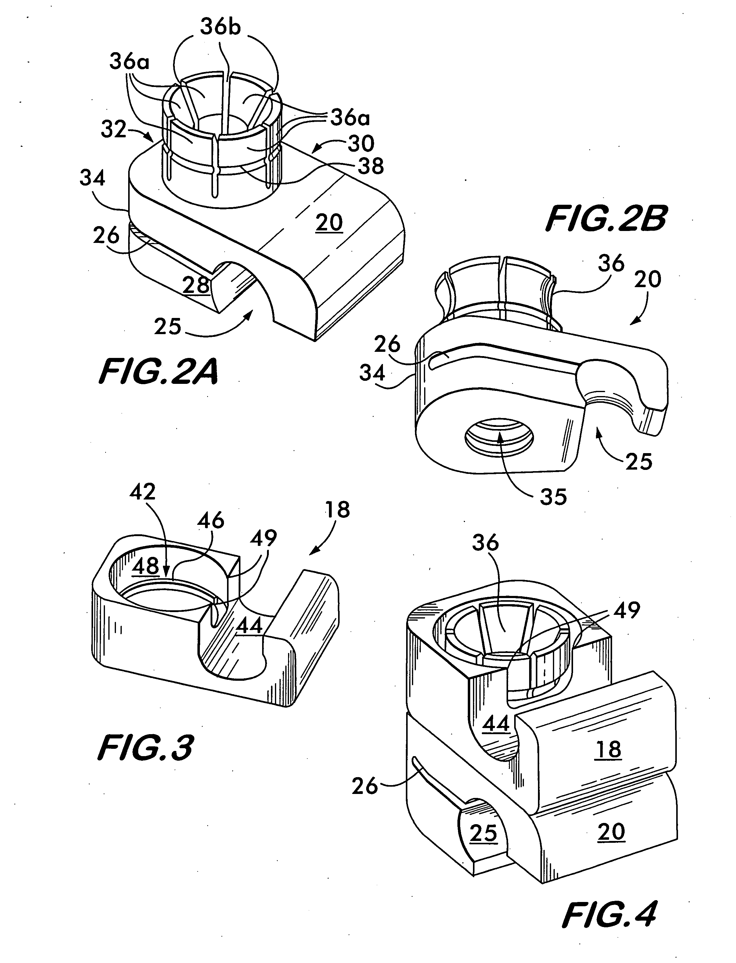
[0036]FIGS. 2A and 2B are upper and lower perspective views of a lower clamping member 20. It comprises a C-shaped spinal rod receiving channel 25 sized to accept a spinal rod 12. A slot 26 that runs the full depth of the clamping member 20 from the front side walls 28 to the rear sidewall 30 ...


PUM


Abstract

The invention is a rod to rod connector that can be used to interconnect two generally parallel spinal rods of a spinal rod and anchor system. The connector comprises a transverse rod and two pairs of clamping bodies, one for each spinal rod. Each pair connects one of the longitudinal spinal rods to the transverse rod in infinitely adjustable angular relationship. One of the two clamping bodies of each pair comprises a C-shaped channel for accepting the spinal rod. The channel is in communication with a slot that defines a hinge. A threaded screw hole passes transversely through the slot and permits a screw to squeeze the hinge, thereby causing the C-shaped channel to close around and clamp the rod. The second clamping body is similar to the first except that there is no slot or hinge and the screw hole preferably is not threaded, but includes a countersink for seating a chamfered screw head. Also, an angular portion of the screw hole intersects the C-shaped channel. The two clamping bodies are aligned with each other so that their screw holes are coaxial so that a single screw can pass through both holes thereby clamping both rods in the C-shaped channels and fixing the angle between the two clamping bodies and, hence, the two rods. The first clamp clamps the spinal rod by squeezing the hinge to cause the C-shaped channel to squeeze around the rod. The second clamp clamps the transverse rod by virtue of the bottom of the screw head bearing down on the transverse rod over the portion of the screw hole that intersects the C-shaped channel.

Description

CROSS REFERENCE TO RELATED APPLICATION [0001] This application claims the priority of U.S. Provisional Application No. 60 / 710,389, filed Aug. 23, 2005, which is hereby incorporated herein by reference.BACKGROUND [0002] 1. Field of the Invention [0003] The invention generally relates to orthopedic devices. More specifically, the present invention is a surgical tool or medical construct used with spinal rods for the purpose of spinal fixation and correction of spinal curvature. [0004] 2. Description of Related Art [0005] Spinal rods are often used for spinal fixation, including for correction of scoliotic curves. Fixation using such rods often involves implantation of rods and attaching them to the spine by anchors in the form of hooks and / or screws. Usually, a pair of rods are placed on opposite sides of the portion of the spine to be fixed. [0006] Various systems have been developed for cross linking spinal rods to prevent rod migration and to increase stiffness of the paired rod as...

Claims


Application Information

Patent Timeline
IPC IPC(8): A61F2/30
CPCA61B17/645A61B17/7052A61B17/7049
Inventor RICHELSOPH, MARCUSHER, JOHN A.
Owner AESCULAP AG
Why Eureka
Try Eureka