Cinch control device

a control device and cinch technology, applied in the field of cinch control, can solve the problems of insufficient axial travel of the cinch, insufficient single surface of the cinch or jaw assembly, and difficulty in operating the device, so as to accurately control the opening and closing of the cinch, the effect of reducing travel

Inactive Publication Date: 2007-03-01
MICROLINE PENTAX
View PDF22 Cites 313 Cited by
  • Summary
  • Abstract
  • Description
  • Claims
  • Application Information

AI Technical Summary

Benefits of technology

[0009] A feature of the present invention provides a clip applying device that is able to accept two different types of clip cartridges. With such a configuration, clip applying jaws move radially over a greater distance than other clip appliers, such full, positive and consistent control of the jaws is required. Further, limited travel in the axial direction X of a cinch is normally not enough to cover this increased radial travel of the jaws. If cinch travel in the axial direction X is increased, then the surgeon may have difficulty operating the device, since the device may be too long for precise control. Thus, there is no single surface of the cinch or jaw assembly to completely and accurately control the opening and closing of the cinch, when using a cinch with reduced travel.

Problems solved by technology

Further, limited travel in the axial direction X of a cinch is normally not enough to cover this increased radial travel of the jaws.
If cinch travel in the axial direction X is increased, then the surgeon may have difficulty operating the device, since the device may be too long for precise control.
Thus, there is no single surface of the cinch or jaw assembly to completely and accurately control the opening and closing of the cinch, when using a cinch with reduced travel.

Method used


Image

  • Cinch control device
  • Cinch control device
  • Cinch control device

Examples


Embodiment Construction

[0069] The particulars shown herein are by way of example and for purposes of illustrative discussion of the embodiments of the present invention only and are presented in the cause of providing what is believed to be the most useful and readily understood description of the principles and conceptual aspects of the present invention. In this regard, no attempt is made to show structural details of the present invention in more detail than is necessary for the fundamental understanding of the present invention, the description taken with the drawings making apparent to those skilled in the art how the several forms of the present invention may be embodied in practice.

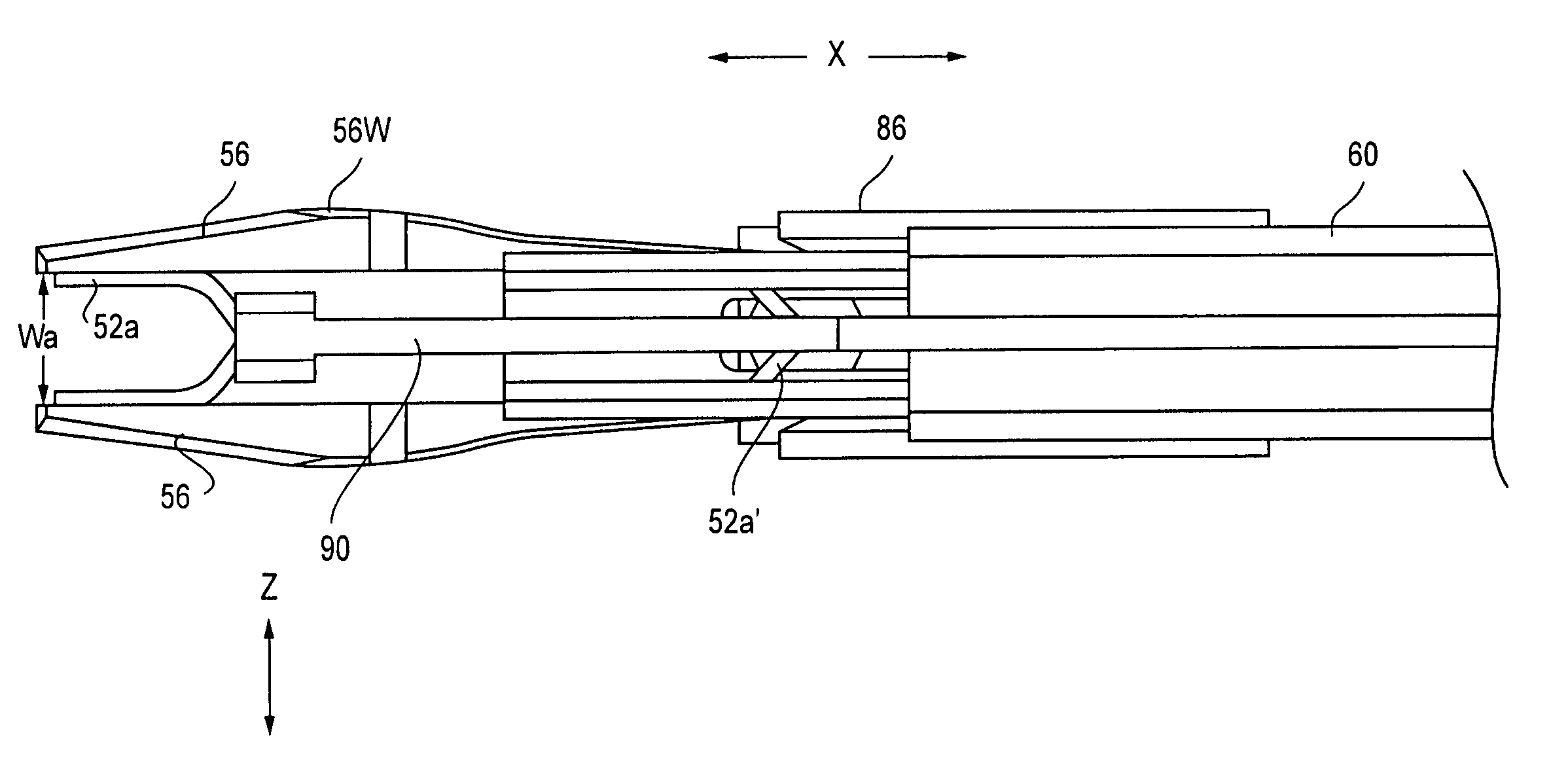
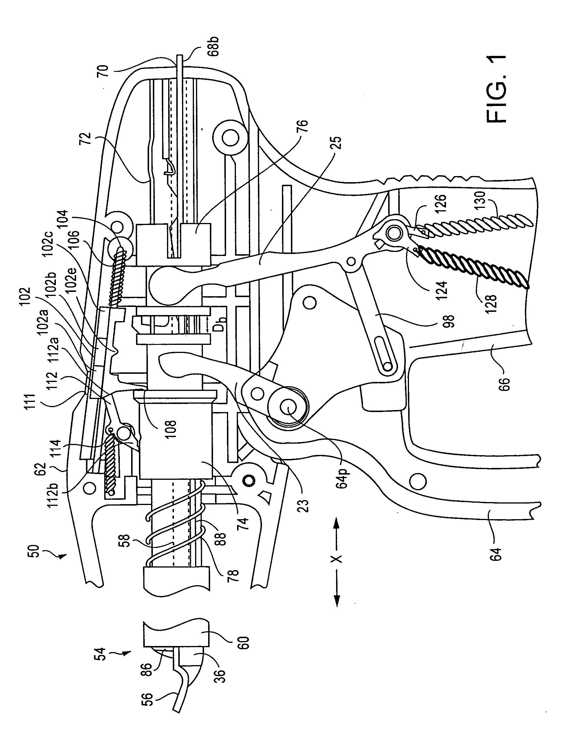
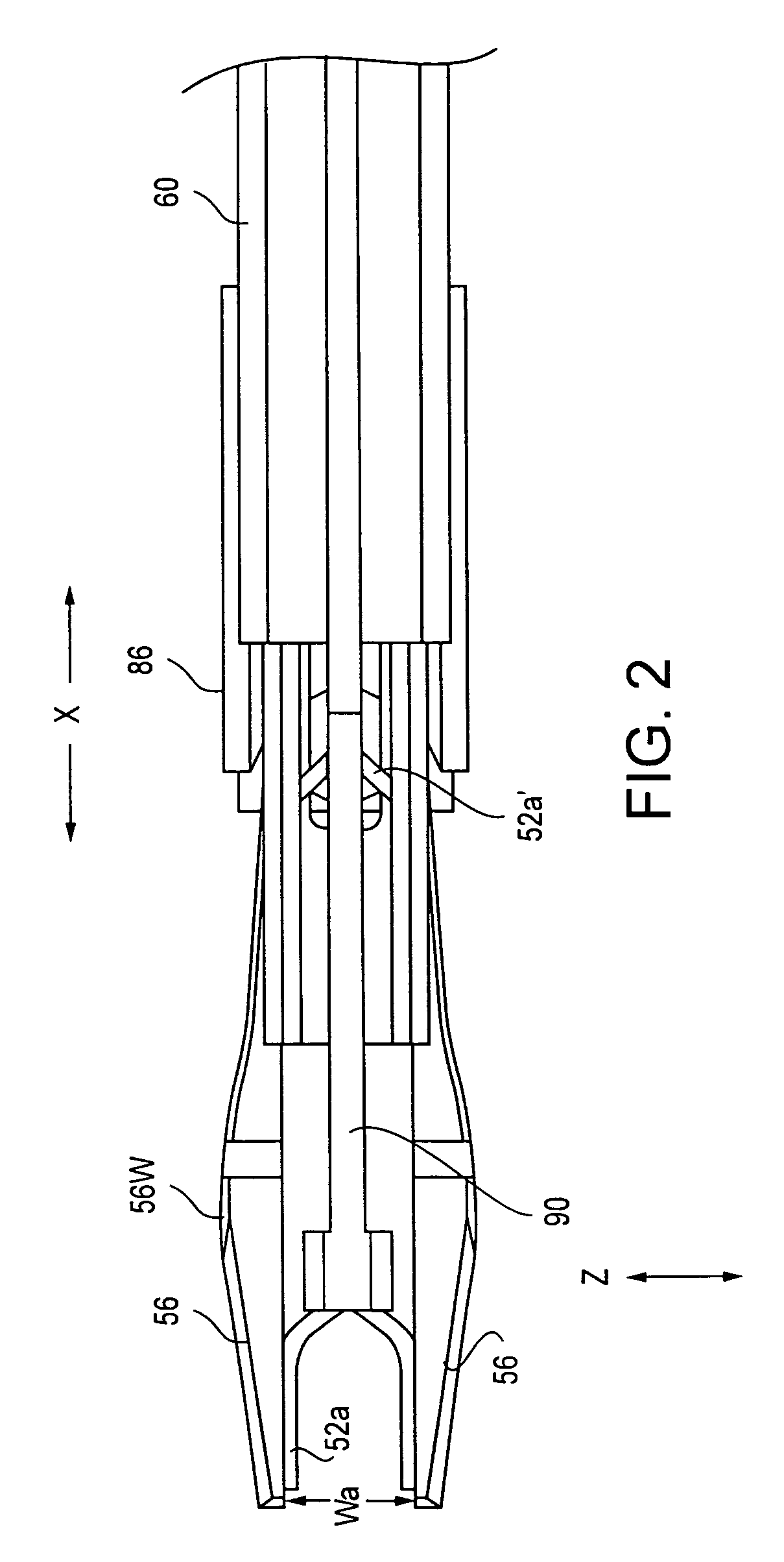
[0070] Referring to the drawings, wherein like characters represent like elements, FIG. 1 shows a clip applying device 50 for applying medical tissue-pinching clips 52a, 52b to tissue. The clip applying device 50 has a patient-engaging distalmost end 54 with a pair of squeezable jaw members (jaws) 56 arranged thereon. A...


PUM


Abstract

A mechanism for opening and closing jaws of a medical instrument. The mechanism includes a cinch configured to selectively move in opposite directions along a longitudinal axis, the cinch comprising a pair of control members each having an inner control surface and an outer control surface, and a jaw assembly having a pair of jaw arms, each jaw arm comprising an inner engagement surface configured to slidingly engage with a respective the outer control surface, and an outer engagement surface configured to slidingly engage with a respective inner control surface.

Description

BACKGROUND OF THE INVENTION [0001] 1. Field of the Invention [0002] The present invention is related to a cinch control, and more particularly relates to a cinch control device for medical clip applying device. [0003] 2. Background and Material Information [0004] Laparoscopic surgery is generally defined as minimally invasive surgery upon a patient, utilizing small or miniaturized medical devices by which body tissue is cut, removed or cauterized by small manipulable tools / devices through small incisions or openings within the patient's body. One such tool is a clip applier, which is used to grasp and / or crimp / seal tissue by the single hand of an operating surgeon, and is described in commonly-assigned U.S. Patent Publication No. 2003 / 0040759 and U.S. Pat. No. 6,277,131, the entire contents of both documents being expressly incorporated by reference herein. [0005] Prior art clip appliers have a patient-engaging distalmost end with a pair of squeezable jaws arranged on the distal end...

Claims


Application Information

Patent Timeline
Patent Type & Authority Applications(United States)
IPC IPC(8): A61B17/10
CPCA61B17/10A61B2017/2937A61B2017/2933A61B17/122
Inventor MENN, PAVELTHEROUX, MARCALISKI, PETER
Owner MICROLINE PENTAX
Why Eureka
Try Eureka