Four-leaflet stented mitral heart valve

Active Publication Date: 2007-03-01
EDWARDS LIFESCIENCES CORP
View PDF16 Cites 156 Cited by
  • Summary
  • Abstract
  • Description
  • Claims
  • Application Information

AI Technical Summary

Benefits of technology

[0012] The present invention provides a prosthetic heart valve for implant at a valve annulus, comprising a support frame defining a non-circular orifice about an axis along an inflow-outflow direction. Four separate flexible leaflets each separately mounted for movement on the support frame to provide a one-way valve in the elliptical orifice. In one embodiment, the support frame defines an elliptical orifice, and the four leaflets may be arranged into pairs of diametrically opposed, symmetric leaflets. In a particular embodiment, each one of the first pair of leaflets is substant

Problems solved by technology

In particular, they have been no commercially successful attempts to modi

Method used


Image

  • Four-leaflet stented mitral heart valve
  • Four-leaflet stented mitral heart valve
  • Four-leaflet stented mitral heart valve

Examples


Embodiment Construction

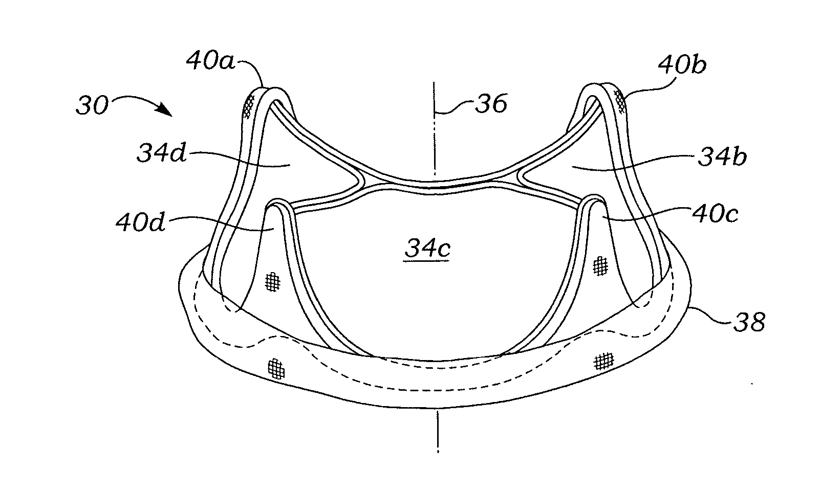
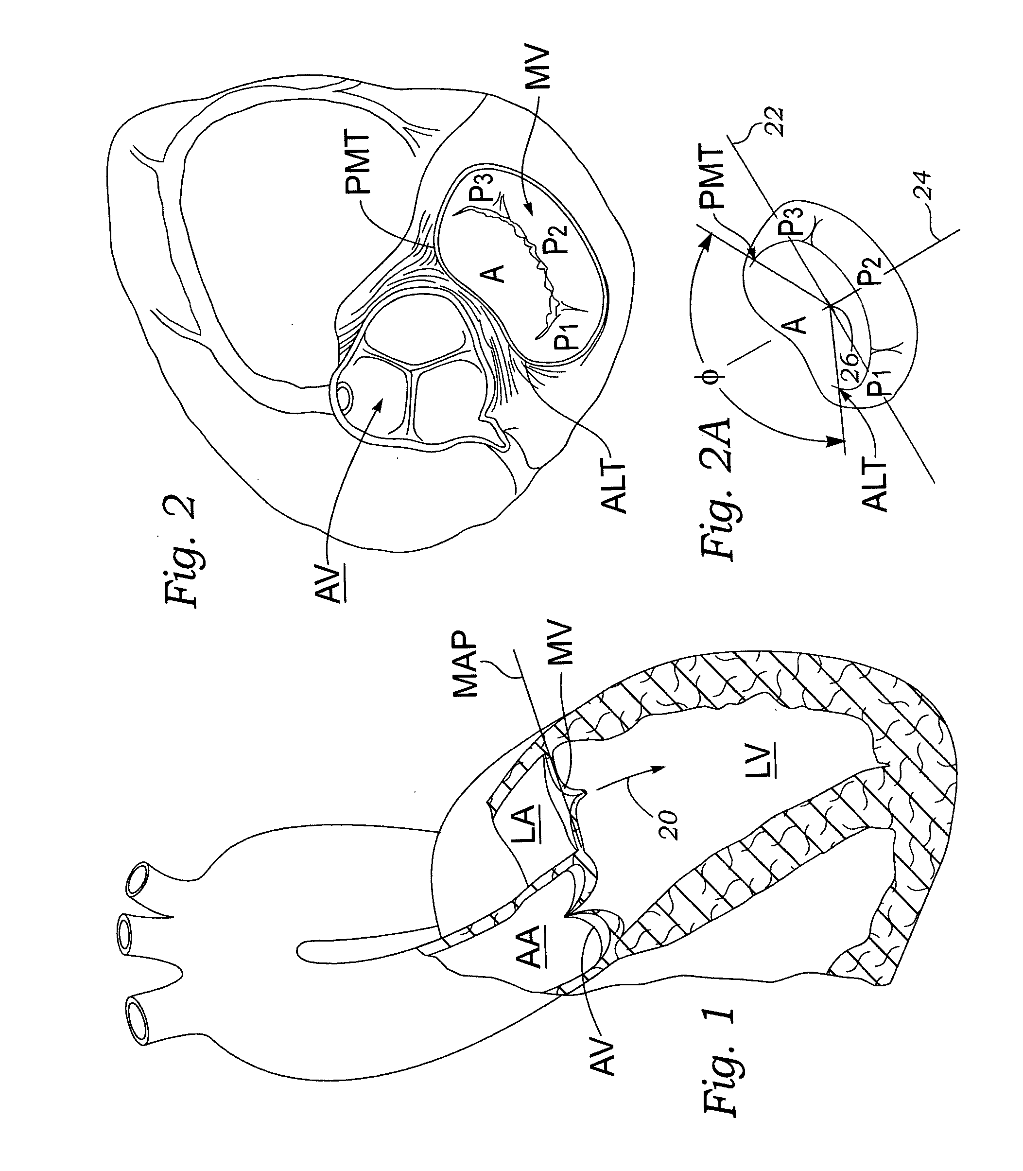
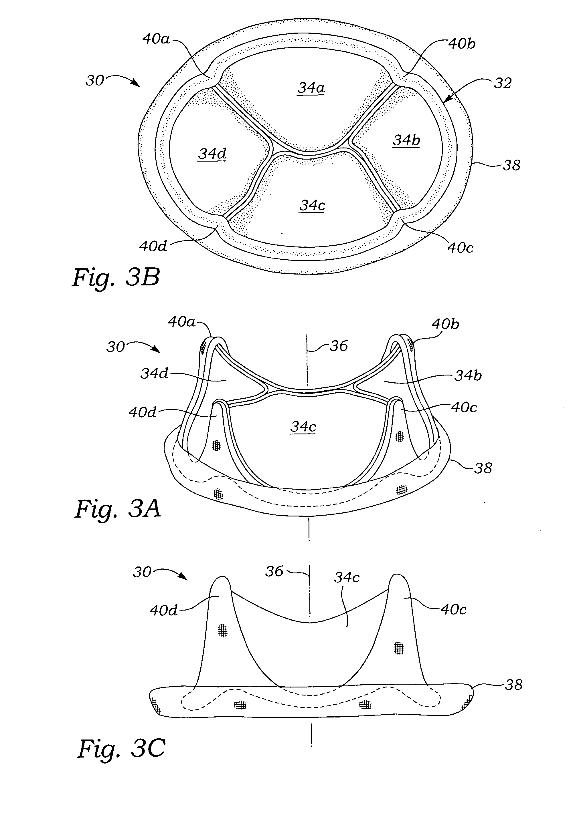
[0027] The present invention pertains to prosthetic heart valves that simulate the natural human heart valve anatomy, in particular for the mitral valve. For instance, the shape of the flow orifice may be non-circular so as to mimic the shape of the mitral annulus in the systolic phase, or there may be four leaflets with one or more substantially smaller than the others. In a preferred embodiment, four leaflets are utilized with two opposed pairs that are substantially different from each other. More specifically, an exemplary heart valve of the present invention includes a first pair and a second pair of leaflets, each pair diametrically opposed across the valve orifice, and wherein each leaflet of the first pair is substantially smaller than either leaflet of the second pair.

[0028] The reader will see from the following description and appended drawings various features of the exemplary valves that are intended to mimic the natural mitral valve. It should be noted, however, that ...


PUM


Abstract

A prosthetic mitral heart valve having four separate flexible leaflets. The heart valve includes a support frame that may be non-circular, for example elliptical or “D-shaped”. The support frame may have an undulating outflow edge defined by four inflow cusps and four outflow commissures to which each of the flexible leaflets attaches. The support frame may comprise an undulating wireform and a surrounding stent defining a structure having four cantilevered posts projecting in the outflow direction to support the four leaflets. The heart valve is designed to be secured in the annulus and function as a standalone unit without papillary muscle connections to the leaflets. The four leaflets may be arranged in two opposed pairs, one pair being smaller than the other pair. The larger pair of leaflets may be identical, or differently sized. Existing sizes of heart valve leaflets may be utilized with the smaller leaflets being at least two leaflet sizes smaller than the larger leaflets in odd millimeter increments.

Description

FIELD OF THE INVENTION [0001] The present invention relates generally to an implantable prosthetic heart valve for the mitral annulus and, more particularly, to a four-leaflet prosthetic heart valve having a non-circular flow orifice. BACKGROUND OF THE INVENTION [0002] The most common locations at which prosthetic heart valves are implanted are the aortic and mitral valves associated with the left ventricle, which generates the higher pressures of the two ventricles. The anatomy of the aortic and mitral valves are quite different, with the former being a tri-symmetric / tri-leaflet structure, and the latter having two dissimilar leaflets. The aortic annulus defines an undulating fibrous structure around substantially a circular ring to support the up-and-down shape of the cusps and commissures of the native leaflets. On the other hand, the mitral annulus has a somewhat fibrous linear anterior aspect across the septum of the heart from the aortic valve, but the posterior aspect, which ...

Claims


Application Information

Patent Timeline
IPC IPC(8): A61F2/24
CPCA61F2/2412A61F2/2418
Inventor JOHNSON, DERRICK
Owner EDWARDS LIFESCIENCES CORP
Why Eureka
Try Eureka