
Buckle with pivoting and sliding strap securing bar

a sliding strap and buckle technology, applied in the field of buckles, can solve the problems of requiring extra work on the part of the user the belt loosening unexpectedly, and the user's inability to loosen the belt, so as to prevent inadvertent slippage of the strap and easily loosen the strap

Active Publication Date: 2007-03-08
DURAFLEX HONG KONG
View PDF7 Cites 7 Cited by
  • Summary
  • Abstract
  • Description
  • Claims
  • Application Information

AI Technical Summary

Benefits of technology

The invention is a buckle that prevents the strap from slipping and allows for easy adjustment of the strap. It has a male and female portion with a slidable strap gripping bar that can be locked in position to prevent slippage. The strap gripping bar has teeth that grip the strap and a pushing surface that connects to the male portion. The female portion may also have a strap retaining bar and the strap gripping bar may have protrusions and indentations to securely hold the strap. The technical effects of this invention are that it prevents accidental slippage of the strap and allows for easy adjustment of the strap with a simple buckle design.

Problems solved by technology

One problem encountered with these basic buckles is that the straps often slip out of their initially tensioned state, and cause the belt to loosen unexpectedly.
Another problem is that it can often be difficult to loosen the belt when desired, because the straps can sometimes be stuck on the bars, especially if the strap retaining bars are spaced close to the buckle body.
While this is an effective way to prevent slippage, it requires extra work on the part of the user to loosen the belt.
Additionally, pivoting the bar may require more dexterity than the user possesses, especially in low light or when the buckle is in motion.

Method used


Image

  • Buckle with pivoting and sliding strap securing bar
  • Buckle with pivoting and sliding strap securing bar
  • Buckle with pivoting and sliding strap securing bar

Examples


Embodiment Construction

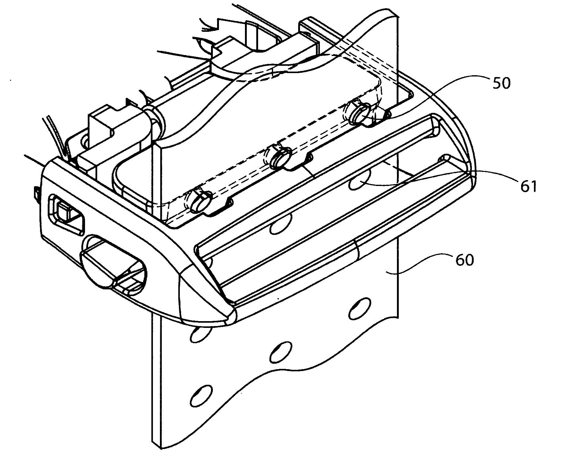
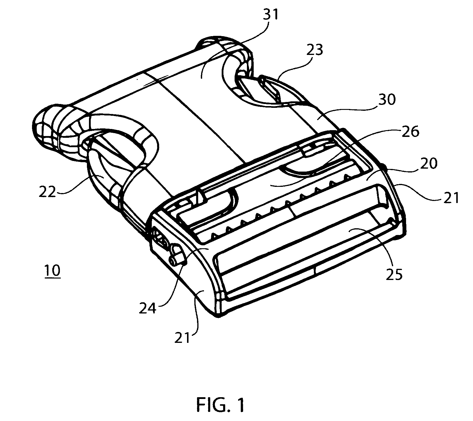
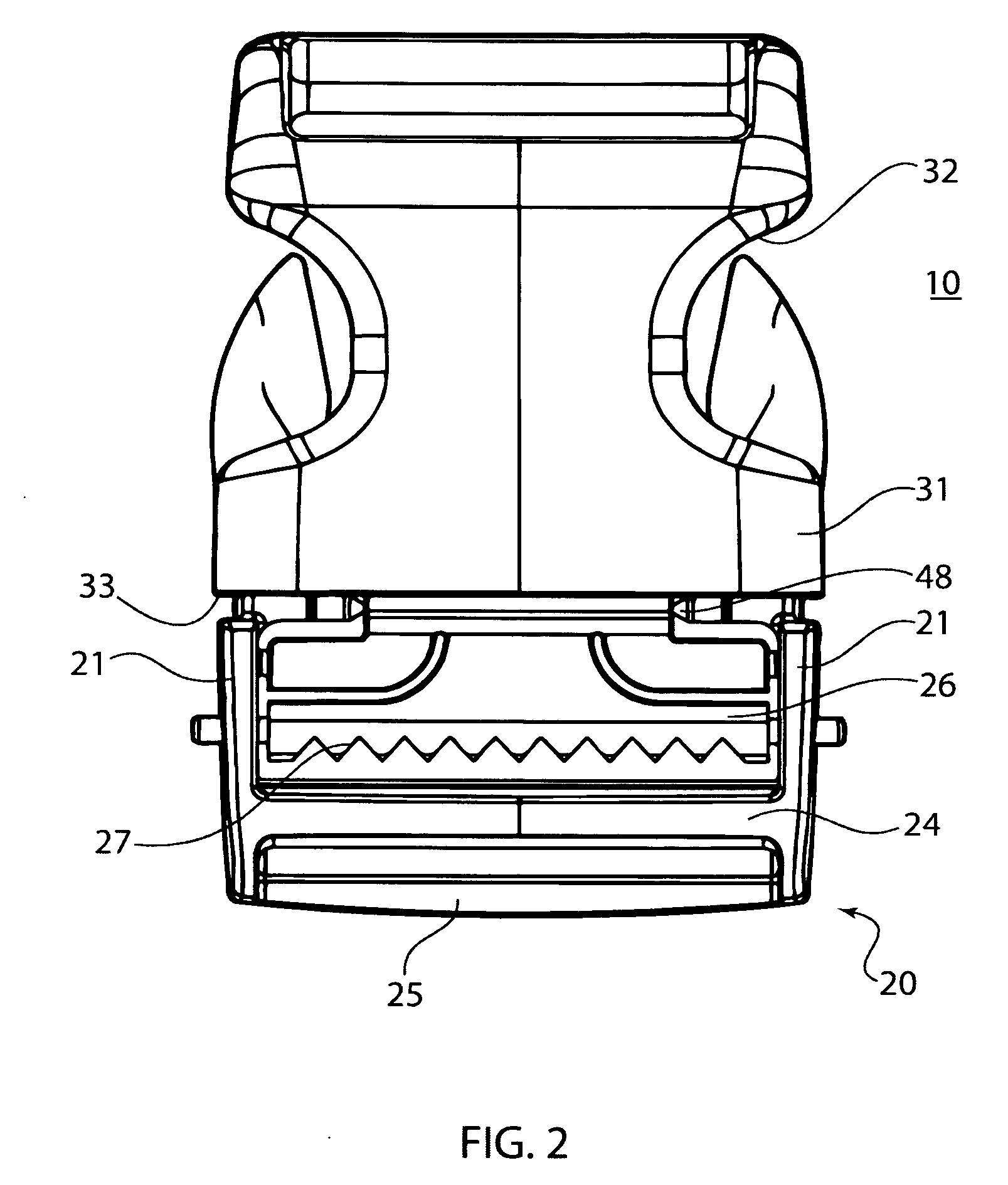
[0032] Referring now in detail to the drawings, FIGS. 1-3 show buckle 10 in a locked position. Buckle 10 comprises a male portion 20 and a female portion 30. Male portion 20 has two sidewalls 21, two locking arms 22, 23, a first strap retaining bar 24 and a second strap retaining bar 25. A slidable or pivotable strap gripping bar 26 is disposed adjacent first strap retaining bar 24.

[0033] Strap gripping bar 26 has a plurality of teeth 27 disposed along a face adjacent strap retaining bar 24. Strap gripping bar 26 is connected to male portion 20 via two protrusions 28, 29 on each end of strap gripping bar 26, which extend through two apertures 40,41 on each of sidewalls 21 of male portion 20. The shape of the protrusions 28, 29 and of apertures 40, 41 are such that strap gripping bar 26 can slide and / or pivot between a gripping position and a release position, which will be described in detail below. A detailed picture of male portion 20 is shown in FIG. 4, and a detailed picture of...


PUM


Abstract

A buckle having a male portion and a female portion. The male portion has two sidewalls, first and second retaining bars and at least one locking arm. There is a slidable and pivotable strap gripping bar disposed adjacent the first strap retaining bar. The strap gripping bar is adapted to slide between a release position and a gripping position. The female portion comprises a hollow body with an open end and at least one locking slot for receiving the locking arm. When the male portion is inserted into the female portion, the locking arm locks into the locking slot and the female portion pushes the strap gripping bar into a gripping position, which grips a strap threaded through the retaining bars, and prevents the strap from slipping. When the male portion is released from the female portion, the strap gripping bar slides into the release position and allows adjustment of the strap.

Description

CROSS REFERENCE TO RELATED APPLICATIONS [0001] This application is a continuation-in-part of U.S. patent application Ser. No. 11 / 098,057, filed on Apr. 4, 2005.BACKGROUND OF THE INVENTION [0002] 1. Field of the Invention [0003] The invention relates to a buckle for use in belts, seat belts, backpacks, or other uses. In particular, the invention relates to a buckle with a slidable bar that secures the buckle to a strap to prevent inadvertent slippage of the strap during use. [0004] 2. The Prior Art [0005] In conventional plastic buckles that are used in belt applications, i.e., to secure two straps together, each side of the buckle typically has a bar around which each strap is threaded to attach the strap to the buckle piece. An example of such a buckle is shown in United States Design Patent No. D401,533, the disclosure of which is herein incorporated by reference. [0006] One problem encountered with these basic buckles is that the straps often slip out of their initially tensioned...

Claims


Application Information

Patent Timeline
Patent Type & Authority Applications(United States)
IPC IPC(8): A44B11/25
CPCA44B11/006A44B11/08Y10T24/4042Y10T24/4736Y10T24/45581Y10T24/4016Y10T24/45524Y10T24/45529B42F5/00B60R11/00B60R2011/004B60R2011/0049
Inventor ANSCHER, JOSEPH
Owner DURAFLEX HONG KONG
Learn More