Landing gear for a hovercraft

a hovercraft and landing gear technology, applied in the field of landing gear or landing mechanism of a micro aircraft, can solve the problems of sideways translation and destabilizing the landing process, and achieve the effect of simple passive operation

Inactive Publication Date: 2007-03-08
HONEYWELL INT INC
View PDF10 Cites 36 Cited by
  • Summary
  • Abstract
  • Description
  • Claims
  • Application Information

AI Technical Summary

Benefits of technology

[0013] Another advantage of the present invention is that it is lightweight.
[0014] Yet another advantage of the present invention is that it is compliant.
[0015] Another advantage of the present invention is that it is stable.

Problems solved by technology

If a hovercraft is required to adopt a non-vertical orientation of the vehicle body to facilitate landing, sideways translation will occur destabilizing the landing process.

Method used


Image

  • Landing gear for a hovercraft
  • Landing gear for a hovercraft
  • Landing gear for a hovercraft

Examples


Embodiment Construction

(Best Modes for Carrying out the Invention)

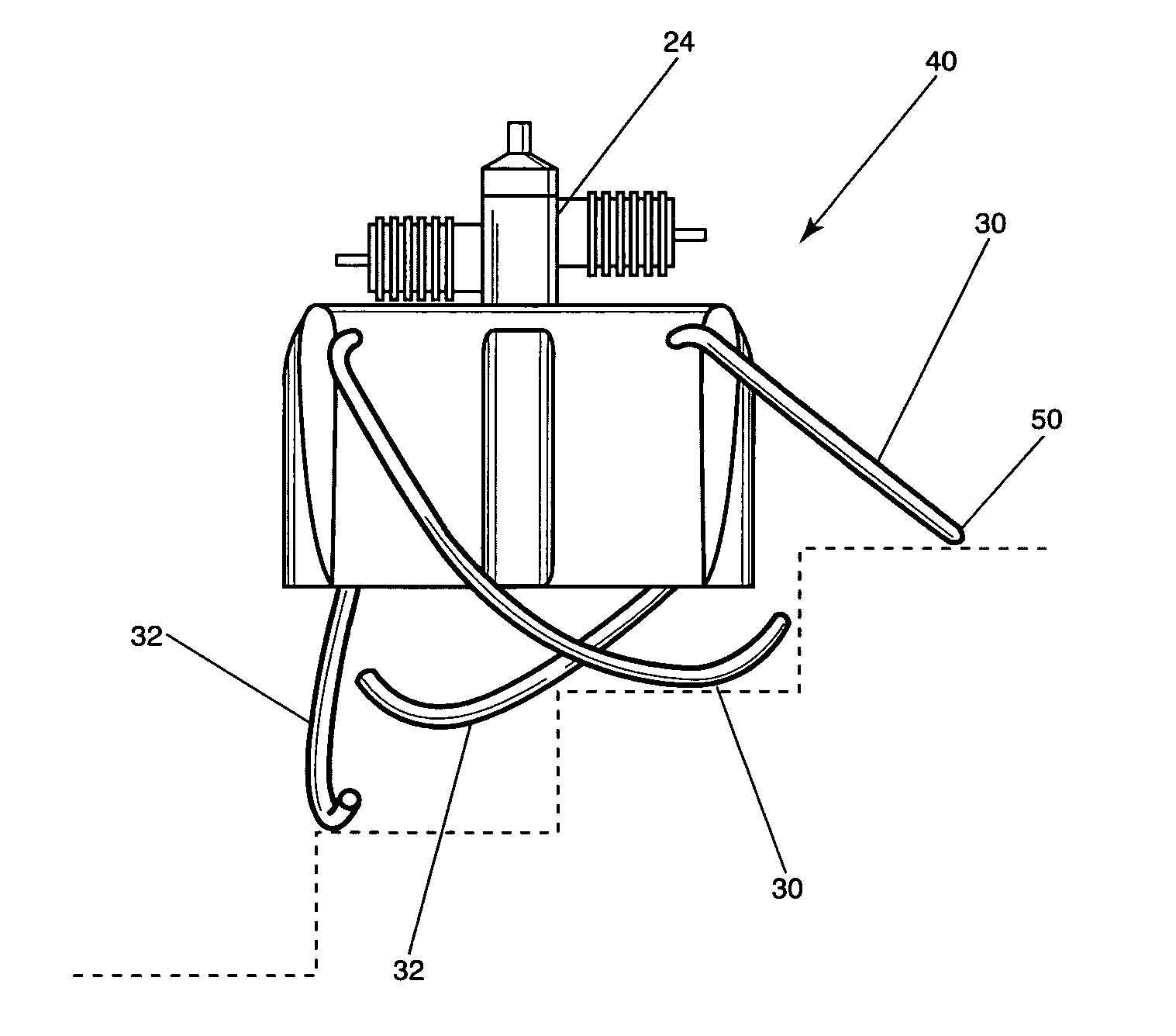
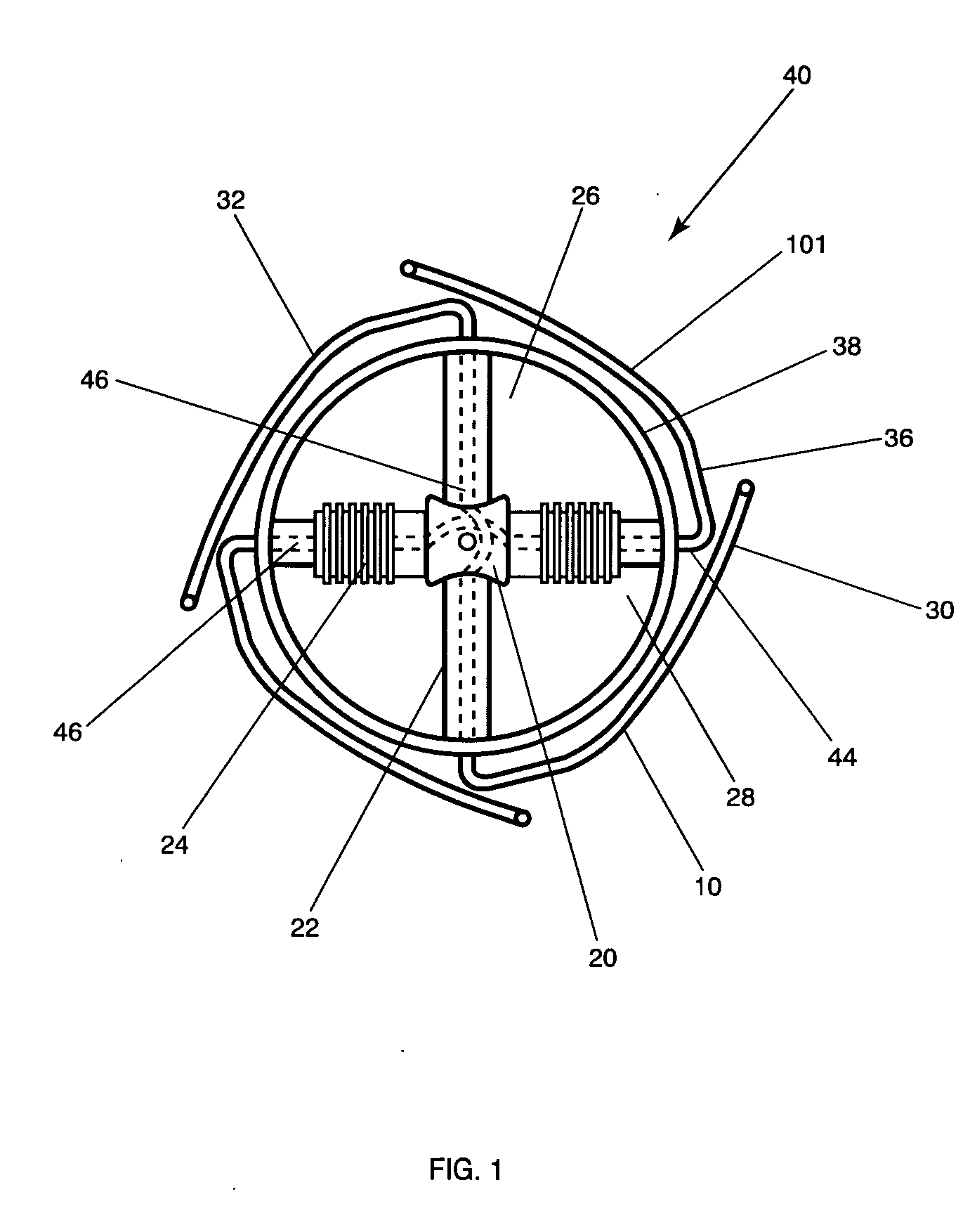
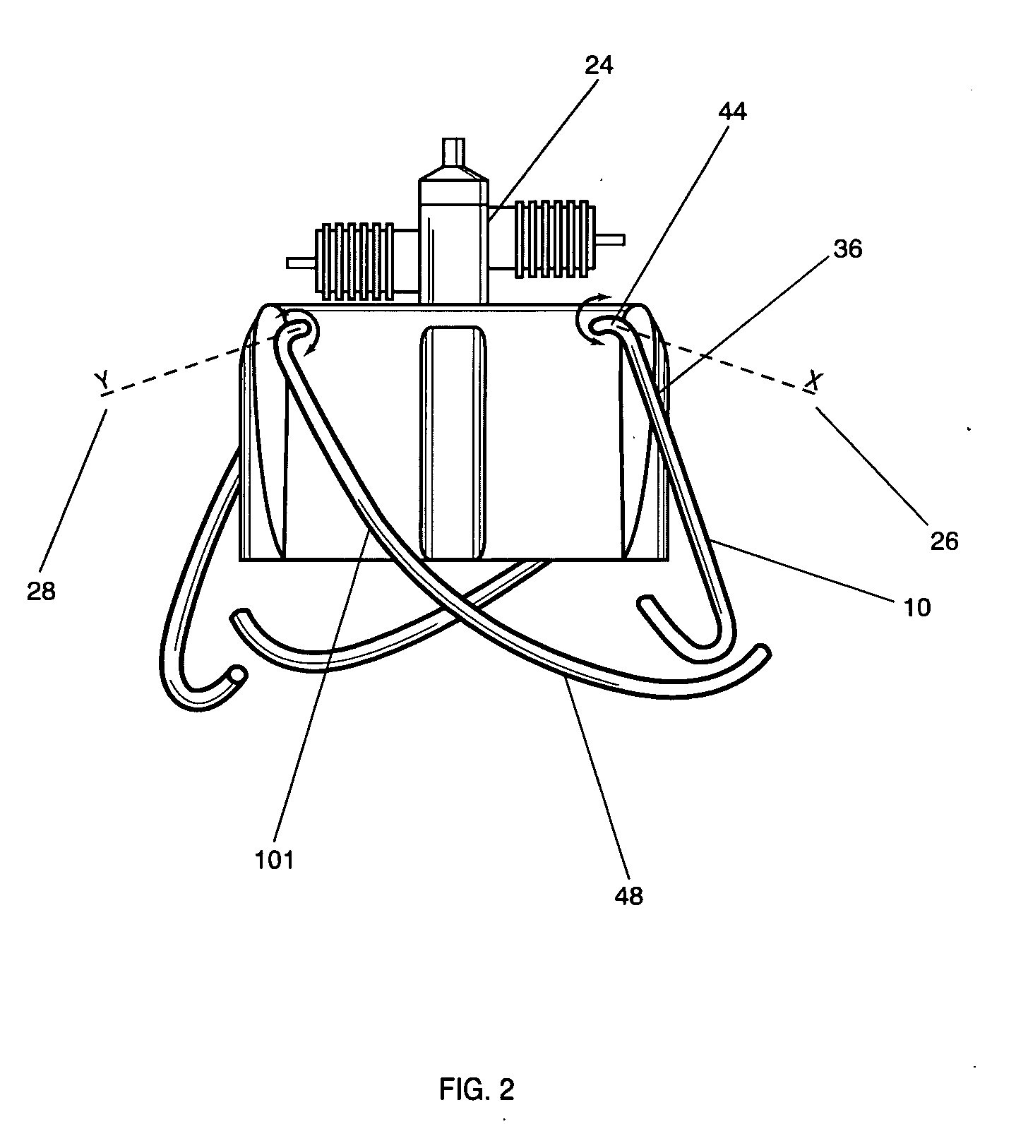
[0022] The present invention is a set of self-leveling legs for hovercraft 40 or other type of vehicle that maintains the vertical orientation of the hovercraft on an uneven or sloped surface. The preferred embodiment of the invention is shown in FIGS. 1 and 2. FIG. 1 shows a top view of the hovercraft with the preferred landing gear. FIG. 2 shows a side view of the embodiment of FIG. 1. In this embodiment two pair of landing leg assemblies 10 and 10′ are shown crisscrossing near the center of hovercraft 20 with offsets to clear the motor shaft. As show in FIG. 1 landing leg assemblies 10 and 10′ can be inserted or disposed within cross bars 22 or the like which act as motor mounts for attaching a motor 24. Landing leg assembly 10 needs to rotate about the X axis 26 and landing leg assembly 10′ about Y axis 28. The basic kinematics of the present invention is the displacement of one landing leg 30 upwards is connected to the opposite leg 3...


PUM


Abstract

Self-leveling legs are used to accommodate landing a ducted fan hovercraft on a sloped surface such as a roof-top. These legs move to accommodate a variation of slope within their range of motion irrespective to the azimuth of the vehicle body. The configuration and operation of the landing legs allow the hovercraft to land in a stable fashion with the hovercraft vehicle body maintained in a vertical orientation. The basic kinematics of the present invention is the displacement of one landing leg upwards is connected by a horizontal member to the opposite leg and displaces it downwards, and visa-versa. Planar surface contact is accomplished by the unique curvature of the legs and the splay of the legs from the vehicle body.

Description

CROSS-REFERENCE TO RELATED APPLICATIONS [0001] This application is based on U.S. Provisional Application Serial No. 60 / 688,911 entitled “Means for Landing a Hover-Craft on a Sloped Surface”, filed on Jun. 9, 2005, the teachings of which are incorporated herein by reference.GOVERNMENT RIGHTS [0002] The U.S. Government has a paid-up license in this invention and the right in limited circumstances to require the patent owner to license others on reasonable terms as provided for by the terms of HR0011-05-C-0043 awarded by the Defense Advanced Research Project Agency.BACKGROUND OF THE INVENTION [0003] 1. Field of the Invention (Technical Field) [0004] The present invention relates to landing gear and more particularly to a landing gear or landing mechanism for a micro air-vehicle (MAV) or hovercraft that allows vehicles to land on sloped or uneven surfaces while maintaining the vertical orientation of the hovercraft body. [0005] 2. Background Art [0006] Presently there are no solutions t...

Claims


Application Information

Patent Timeline
Patent Type & Authority Applications(United States)
IPC IPC(8): B64C25/00
CPCA63H27/02A63H27/12B64C2201/108B64C39/028B64C2201/027A63H27/14B64U10/13B64U30/20
Inventor MANTYCH, GLEN A.GOOSSEN, EMRAY R.
Owner HONEYWELL INT INC
Why Eureka
Try Eureka