Method of illuminating a projecting imager, corresponding system and projector

Inactive Publication Date: 2007-03-08
THOMSON LICENSING SA
View PDF34 Cites 3 Cited by
  • Summary
  • Abstract
  • Description
  • Claims
  • Application Information

AI Technical Summary

Benefits of technology

[0013] More particularly, the object of the invention is to optimize

Problems solved by technology

These techniques present the drawback of

Method used


Image

  • Method of illuminating a projecting imager, corresponding system and projector
  • Method of illuminating a projecting imager, corresponding system and projector
  • Method of illuminating a projecting imager, corresponding system and projector

Examples


Embodiment Construction

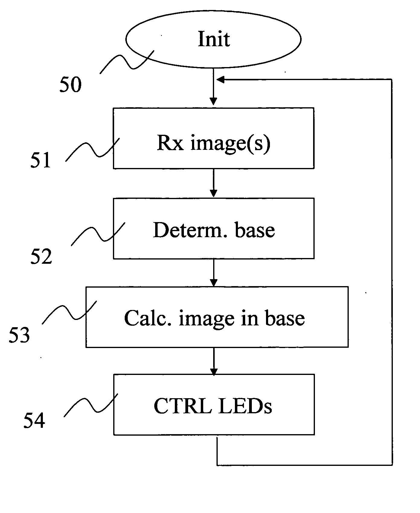
[0046] The main principle of the invention is therefore based on a dynamic management of the illumination beam, the colours of which (nature and / or duration and / or selection of LEDs) depend on each image projected.

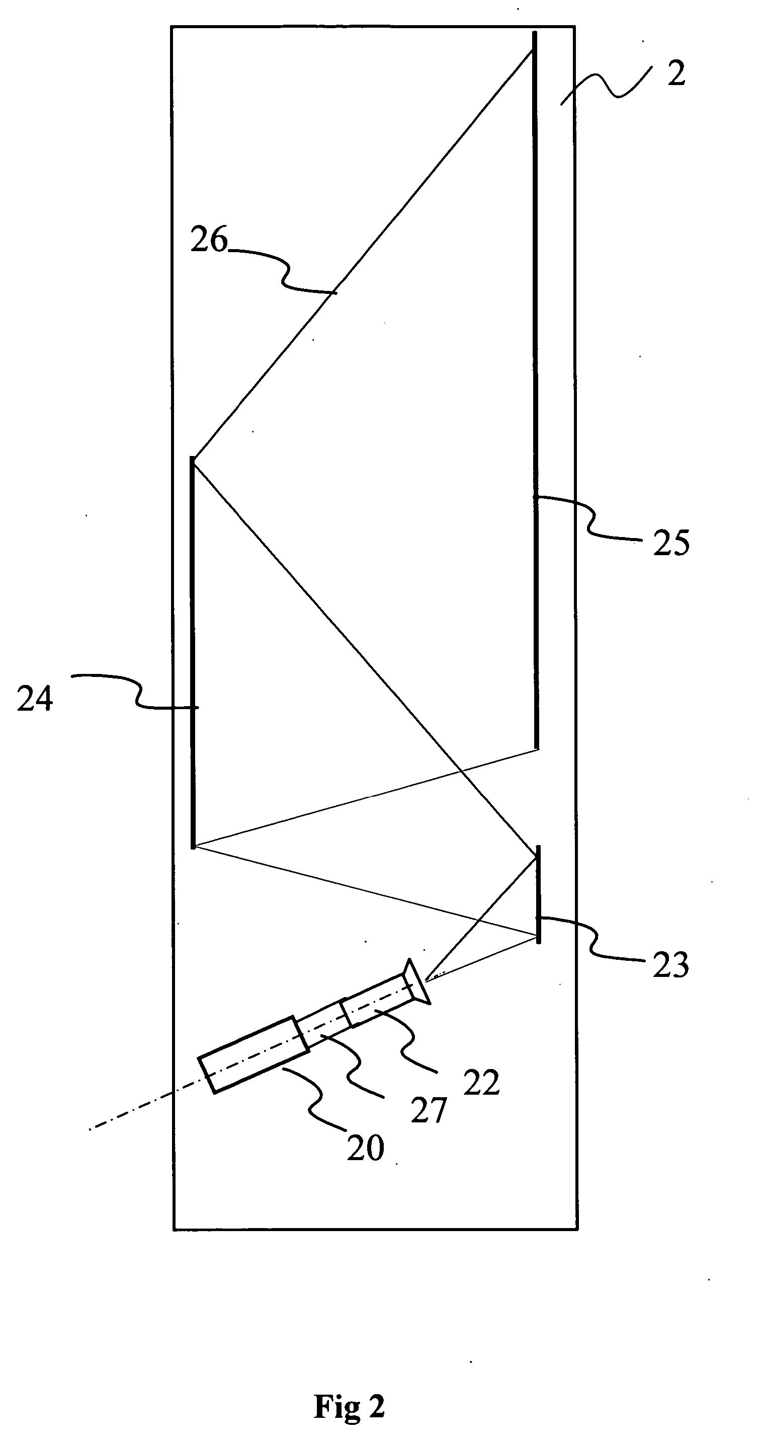
[0047]FIG. 2 is a highly schematic block diagram of an overhead projector 2 according to a first embodiment of the invention.

[0048] The projector 2 comprises: [0049] an illumination system 20; [0050] a lens 21 receiving an illumination beam 26 created by the illumination system 20 and producing a beam 25; [0051] an overhead projection screen 24 lit by the beam 25; and [0052] two folding mirrors 22 and 23 folding the beam 25 and being used to reduce the depth of the projector 2.

[0053] The lens 21, the mirrors 22 and 23 and the screen 24, and their arrangement are well known to those skilled in the art and are not described in any more detail.

[0054]FIG. 3 illustrates in detail the illumination system 20 with transmissive imager and which comprises: [0055] an array of ill...


PUM


Abstract

The invention relates to a method of illuminating an imager for projecting images, implementing light-emitting diodes of different colours, the diodes being designed to provide a beam illuminating the imager. According to the invention, for a set of at least one image, the method comprises: a step for receiving each image of the set; a step for determining a colour base dependent on the set of at least one image, called a secondary colour base; and a step for dynamically controlling the diodes according to said secondary colour base. The invention also relates to a system implementing the method and a projector comprising such a system.

Description

1. FIELD OF THE INVENTION [0001] The invention relates to the field of image projection. [0002] More specifically, the invention relates to an illumination system for an imager (also called micro-display) in a front or overhead video projector. 2. STATE OF THE ART [0003] According to the state of the art, as illustrated by FIG. 1, an illumination system 10 lighting an imager 11 is implemented. [0004] Conventionally, the illumination system 10 comprises; [0005] an illumination source 100 with elliptical reflector, [0006] a coloured wheel 107; [0007] a rectangular guide 102; and [0008] a system of several relay lenses 104 to 106. [0009] The illumination source 100 uses a light beam 101 to light the coloured wheel 107 placed at the input of the rectangular guide 102, at the focus of the elliptical reflector of the source 100. The rectangular guide 102 is used to convert the circular section of the lighting beam into a rectangular section and make the beam spatially uniform. The output ...

Claims


Application Information

Patent Timeline
IPC IPC(8): G03B21/14
CPCH04N9/3197H04N9/3155G03B21/14
Inventor BLONDE, LAURENTO'DONNELL, EUGENE M.SARAYEDDINE, KHALED
Owner THOMSON LICENSING SA
Why Eureka
Try Eureka