Rearview mirror assembly for motor vehicles

a technology for rearview mirrors and motor vehicles, applied in the field of rearview mirrors, can solve problems such as comparatively heavy weigh

Inactive Publication Date: 2007-03-08
LANG MEKRA NORTH AMERICA LLC
View PDF87 Cites 7 Cited by
  • Summary
  • Abstract
  • Description
  • Claims
  • Application Information

AI Technical Summary

Benefits of technology

[0006] The present invention improves the lighter rearview mirror structure of DE 198 40 004 A1 with the necessary stability.

Problems solved by technology

A disadvantage of this type of mirror arrangement is its comparatively heavy weight as found, for example, in the version of EP 0 590 510.

Method used


Image

  • Rearview mirror assembly for motor vehicles
  • Rearview mirror assembly for motor vehicles
  • Rearview mirror assembly for motor vehicles

Examples


third embodiment

[0023] Reference will now be made in detail to the presently preferred embodiments of the invention, examples of which are illustrated in the drawings. The examples are provided by way of explanation of the invention and are not intended as limitations of the invention. For example, features illustrated or described as part of one embodiment can be used on another embodiment to yield yet a Accordingly, it is intended that the present invention include such modifications and variations.

first embodiment

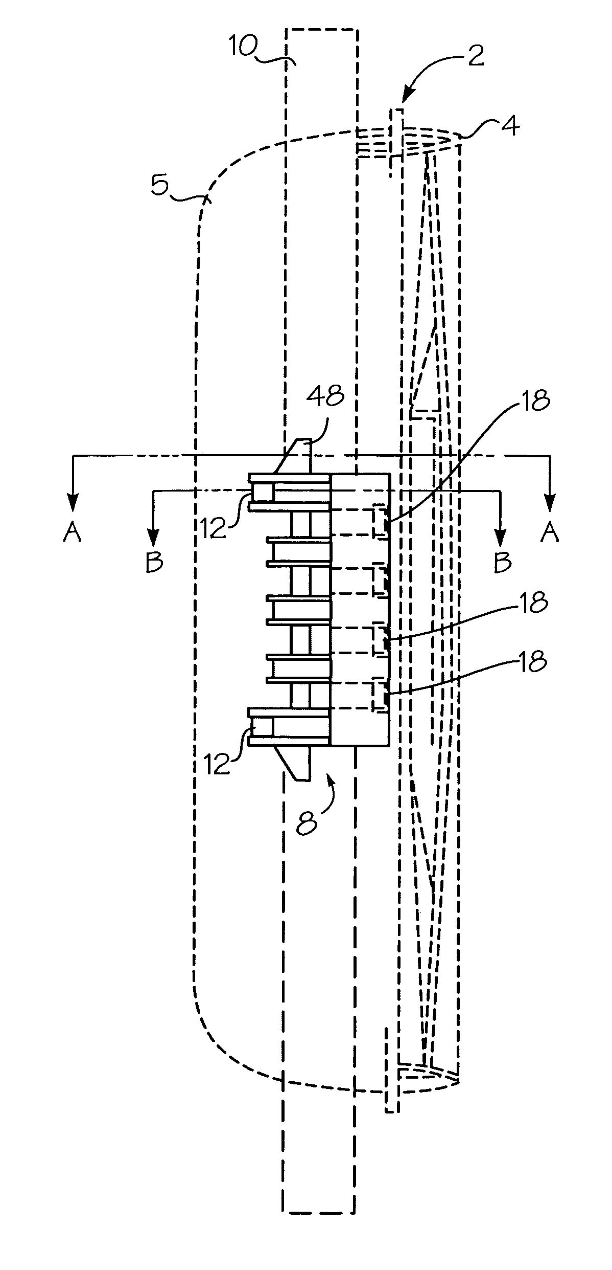
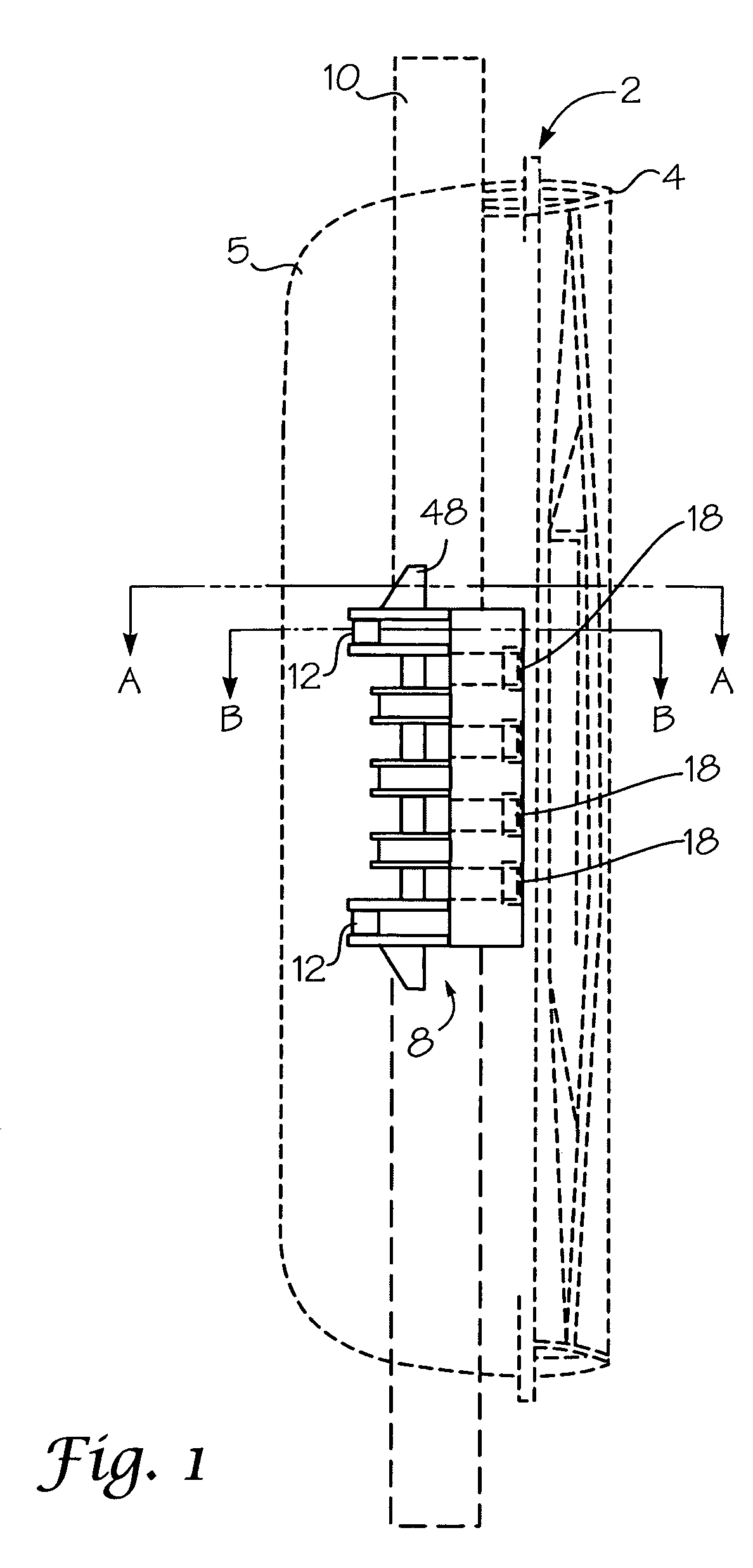
[0024] Turning now to the drawings, the primary first embodiment of the invention as shown in FIG. 1 as a side view, depicting a mirror housing 2, which includes a mirror housing framing element 4 and a mirror housing cover 5. Within the mirror housing 2 is located clamping bracket 12, housing framing element 4 and a mirror element 6 as shown in FIGS. 2 and 3. The entire rear view mirror is fastened by means of clamping connection 8 onto a holding part or holder tube 10. Tube 10 may be a continuous tube or it may be comprised of two tubes separated in the center. The clamping connection 8 comprises, as best seen in FIGS. 2 and 3, a first clamping part in the form of the mirror housing framing or framing element 4 and a second clamping part in the form of a clamping bracket 12.

[0025] As may be inferred from the sectional drawings in FIGS. 2 and 3, the mirror housing framing 4 possesses a through-like recess 14 within which the holder tube or element 10 is partially encased. The clamp...


PUM


Abstract

A rearview mirror assembly for attachment to a holding tube carried by a vehicle. The assembly includes a housing framing configured to encase a portion of the holding tube and to attach with a mirror element. A clamping bracket is also configured to encase a portion of the holding tube and to attach with the housing frame. A projection formed with one of the housing framing and the clamping bracket is positioned to extend into the holding tube when encased by the clamping bracket and housing framing. Connectors are engaged with the housing framing, clamping bracket and the extension locking them in position relative to each other and the holding tube.

Description

CROSS REFERENCE TO RELATED APPLICATION [0001] This application is a Continuation-in-Part of U.S. application Ser. No. 10 / 941,283, filed Sep. 15, 2004, which is a continuation of U.S. application Ser. No. 10 / 767,669, filed Jan. 29, 2004, which is a continuation of U.S. application Ser. No. 09 / 800,114, filed Mar. 6, 2001, now U.S. Pat. No. 6,830,352. Priority is claimed.FIELD OF THE INVENTION [0002] The invention concerns a rearview mirror, especially for motor vehicles. BACKGROUND OF THE INVENTION [0003] DE 198 40 004 A1 discloses a rearview mirror for motor vehicles in which a mirror support element is a carrier plate with a honeycomb structure. The mirror housing with the mirror framing, the mirror element with its pane, and the adjustment apparatus are fastened to the carrier plate. The carrier plate with the honeycomb structure is secured to a holder by means of a clamping mechanism and the holder, in turn, is attached to the body of the vehicle. A mirror of this type possesses a...

Claims


Application Information

Patent Timeline
Patent Type & Authority Applications(United States)
IPC IPC(8): G02B7/182
CPCB60R1/0605
Inventor COURBON, EMMANUELLANG, HEINRICHSEIBOTH, WOLFGANGCENTMAYER, STEFAN
Owner LANG MEKRA NORTH AMERICA LLC
Why Eureka
Try Eureka