Angle reading and setting mechanism

Inactive Publication Date: 2007-03-15
BEALL JERROLD
View PDF24 Cites 15 Cited by
  • Summary
  • Abstract
  • Description
  • Claims
  • Application Information

AI Technical Summary

Benefits of technology

[0006] This invention is a small, convenient, easily used, inexpensive electronic device for reading and setting angles. An electronic angle or position sensing mechanism is mounted together with appropriate circuitry, controls and a digital readout in a small housing having a base and at least one side, and preferably two sides, oriented at right an

Problems solved by technology

Establishing other work piece surface angles is more difficult, particularly with accurate repeatability.
This is because, among other reasons, the scales provided on woodworking tools s

Method used


Image

  • Angle reading and setting mechanism
  • Angle reading and setting mechanism
  • Angle reading and setting mechanism

Examples


Embodiment Construction

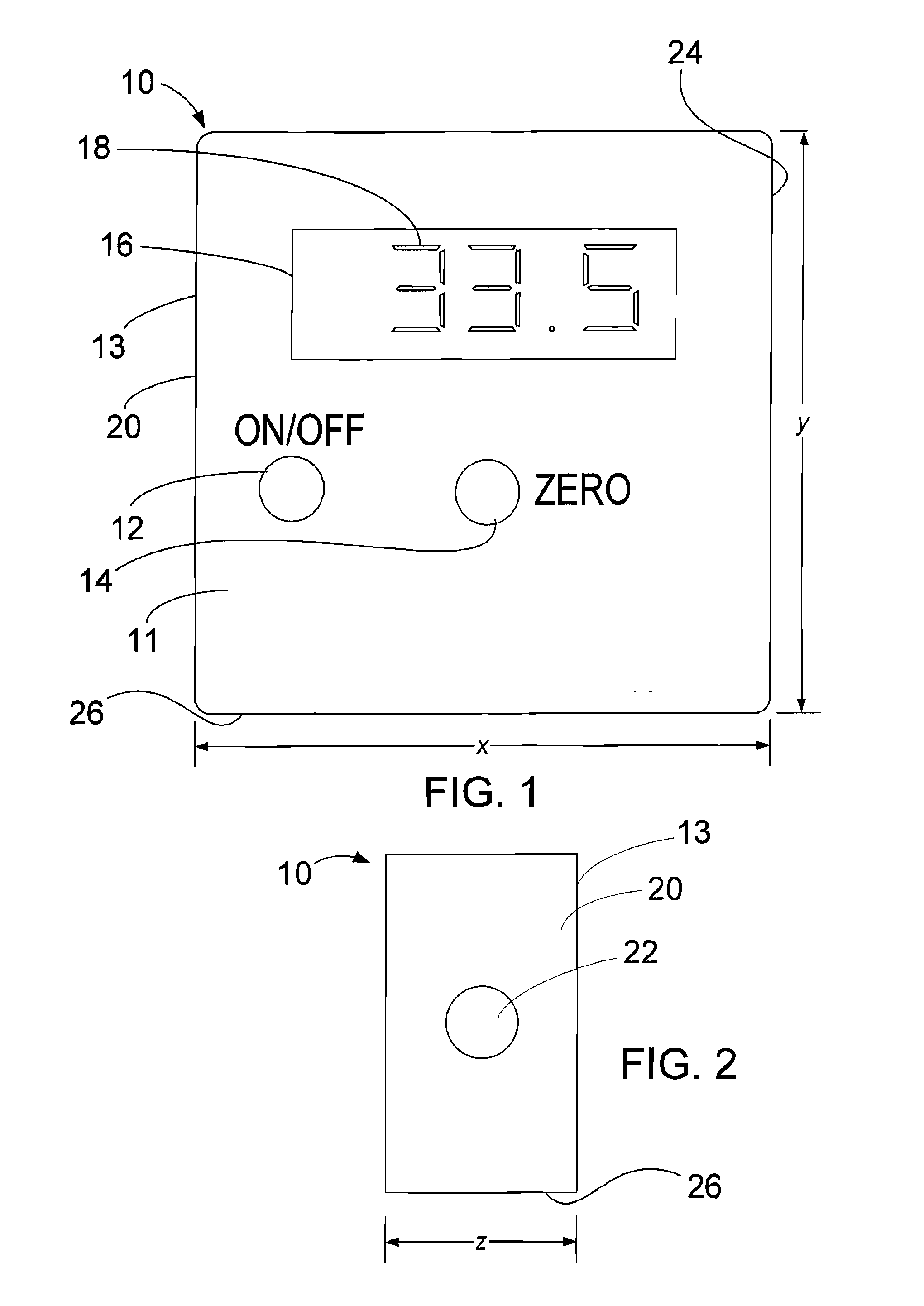
[0014]FIG. 1 is an enlarged front view of one embodiment of the angle reading and setting apparatus 10 of this invention. Positioned on the front 11 of housing 13, the on / off button 12, “zero” button 14, and the window 16 through which numerals 18 may be seen on an LED display.

[0015]FIG. 2 is a side view of the apparatus 10 showing side 20 of housing 13 with a round rare earth magnet 22 fixed (for instance with glue or liquid thread locker such as Locktite brand thread locker) in the side 20 and flush with its surface. Alternatively, the magnets 22 can be mounted slightly below the surface of each side 20 to insure that side 20 will seat solidly against any ferromagnetic surface it contacts. As is apparent from FIG. 1, the sides 20 and 24 of housing 13 are “square” to its bottom 26 (i.e., sides 20 and 24 form a 90° angle with bottom 26). In the embodiment of this invention illustrated in the Figures, the front 13 is square to both the sides 20 and 24 and the bottom 26. This arrange...


PUM


Abstract

Electronic device for reading and setting angles. An electronic angle or position sensing mechanism is mounted together with appropriate circuitry, controls and a digital readout in a small housing having a base and at least one side, and preferably two sides, oriented at right angles to the base. A relatively powerful permanent magnet, such as a rare earth magnet, is fixed in each housing side so that the entire device can be temporarily attached to a ferromagnetic metal surface with one of the magnet-containing housing walls in firm contact with that metal surface, such as the side of a circular saw blade or a machine fence.

Description

REFERENCE DATA [0001] This patent claims priority to U.S. Provisional patent application Ser. No. 60 / 718,423 filed Sep. 19, 2005, which is incorporated herein by reference.FIELD OF THE INVENTION [0002] This invention relates to protractors, angle gauges and other devices for determining the angle between two surfaces, such as a table saw blade and the table surface, or for establishing a specific desired such angle between two surfaces. BACKGROUND OF THE INVENTION [0003] Accurate determination of the angle between two surfaces is frequently important in a wide variety of endeavors, including woodworking, among many others. For instance, in the course of woodworking, it is frequently important to establish one work piece surface at a particular angle relative to another surface of the same work piece. The desired angle is often 90 degrees, which typically is fairly easy to do because woodworking machinery usually is configured to repeatedly cut or form such work piece surfaces at rig...

Claims


Application Information

Patent Timeline
IPC IPC(8): B23Q17/22
CPCG01C9/06
Inventor BEALL, JERROLD
Owner BEALL JERROLD
Why Eureka
Try Eureka