Circular saw

a circular saw and saw blade technology, applied in the field of circular saws, can solve problems such as inconvenience for users, and achieve the effect of saving effort and convenient us

Inactive Publication Date: 2005-03-15
LIAO HUI CHUAN
View PDF5 Cites 35 Cited by
  • Summary
  • Abstract
  • Description
  • Claims
  • Application Information

AI Technical Summary

Benefits of technology

The object of the present invention is to provide a circular saw

Problems solved by technology

However, the motor 16 have to be moved along with the blade supporting fram

Method used


Image

  • Circular saw
  • Circular saw
  • Circular saw

Examples


Embodiment Construction

Before the present invention is described in greater detail, it should be noted that same reference numerals have been used to denote like elements throughout the specification.

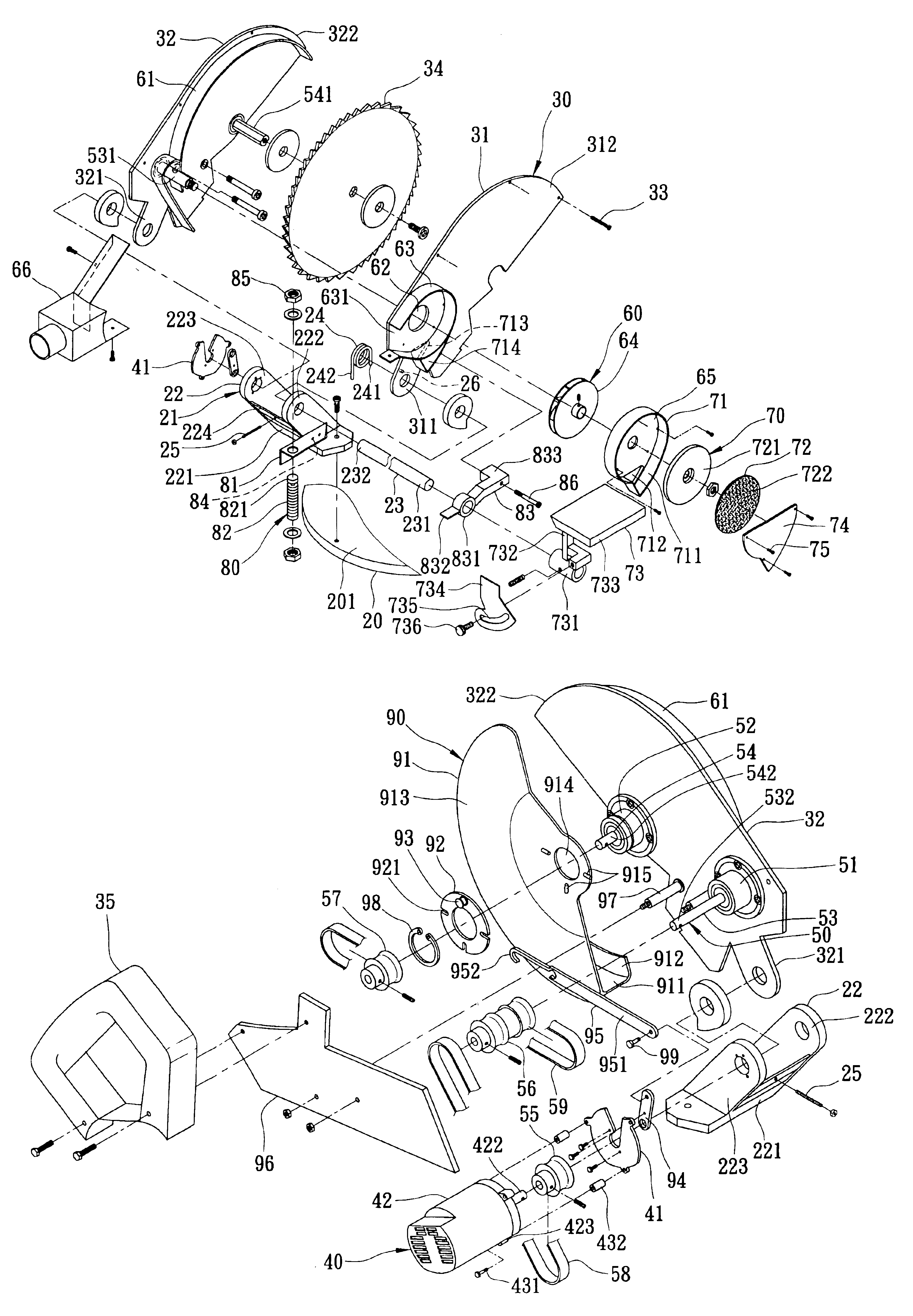
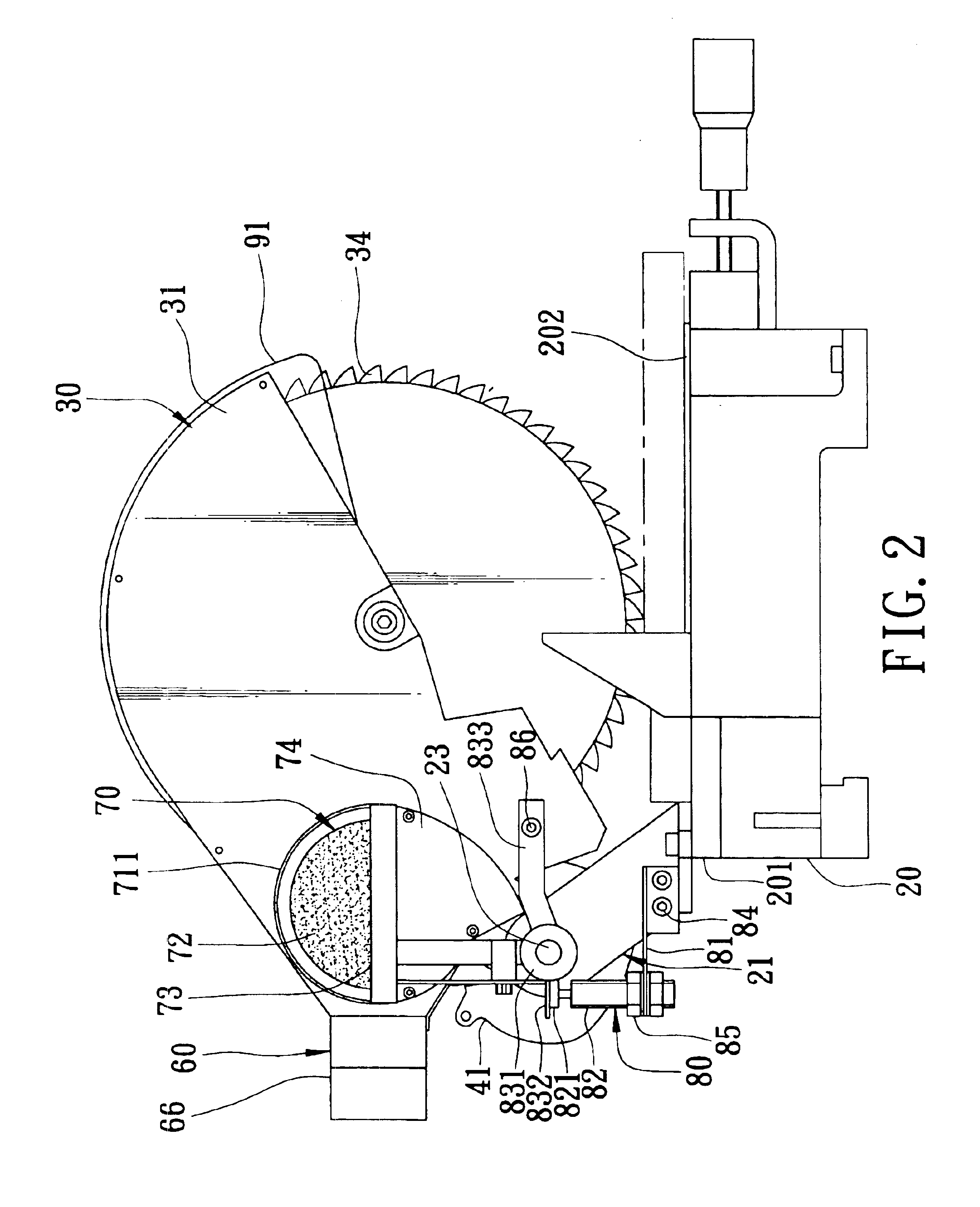
Referring to FIGS. 2 to 5, the preferred embodiment of a circular saw according to the present invention is shown to comprise a worktable 20 having front and rear ends 202,201 opposite to each other in a longitudinal direction, a mounting seat 21 extending from the rear end 201 of the worktable 20 upwardly, a blade supporting unit 30, a driving unit 40, a drive transmission unit 50, a dust collecting unit 60, a grinding unit 70, a damper unit 80, and a blade guarding unit 90.

The mounting seat 21 includes a seat body 22, a pivot shaft 23, and a restricting rod 25. The seat body 22 includes a bottom portion 221, a pair of side plates 222,223 extending upwardly from the bottom portion 221, and a blocking portion 224 interposed between the side plates 222,223. The pivot shaft 23 is secured on top ends of the side...


PUM

PropertyMeasurementUnit
Forceaaaaaaaaaa

Abstract

A circular saw includes a worktable, a mounting seat extending upwardly from the worktable for mounting a motor thereon, a blade supporting unit pivotally mounted on the mounting seat at a pivot end so that an opposite free end is turnable to be close to and away from the worktable, and a saw blade shaft mounted rotatably on the blade supporting unit about a blade axis parallel to an output shaft axis of an output shaft of the motor and having a saw blade mounted thereon. The saw blade shaft is coupled to the output shaft by a drive transmitting unit which transmits driving force of the output shaft to the saw blade shaft so as to rotate the saw blade.

Description

CROSS-REFERENCE TO RELATED APPLICATIONThis application claims priority of Taiwanese Application No. 092219290, filed on Oct. 30, 2003.BACKGROUND OF THE INVENTION1. Field of the InventionThis invention relates to a circular saw, more particularly to a circular saw which includes a motor that is mounted on a mounting seat extending from a worktable, and a circular saw blade that is pivotally mounted to the mounting seat so as to be turned toward and away from the worktable.2. Description of the Related ArtReferring to FIG. 1, a conventional circular saw 10 is shown to include a worktable 11, a mounting seat 12 mounted on a rear end of the worktable 11, a blade supporting frame 14 pivotally mounted on the mounting seat 12 by a pivot member 13 at a pivot end such that an opposite free end is turnable toward and away from the worktable 11, a circular saw blade 15 mounted rotatably on the blade supporting frame 14, a motor 16 mounted on the blade supporting frame 14 to drive the saw blade...

Claims


Application Information

Patent Timeline
IPC IPC(8): B24B23/02B24B23/00B24B27/06B23D45/04B23D47/12
CPCB23D45/042B24B27/065B24B23/02B23D47/12Y10T83/7788
Inventor LIAO, JUEI-SENG
Owner LIAO HUI CHUAN
Why Eureka
Try Eureka