Connector for concrete panels

a technology of connecting rods and concrete, which is applied in the direction of building reinforcements, constructions, building components, etc., can solve the problems of difficult to obtain the degree of accuracy or the desired holding power using these devices, the structure is not entirely satisfactory, and the wings are not well retained, so as to reduce the cost of assembly, simple and inexpensive manufacturing, and the effect of reducing the cost of assembly

Inactive Publication Date: 2007-03-15
SAMPLE ALAN H
View PDF4 Cites 12 Cited by
  • Summary
  • Abstract
  • Description
  • Claims
  • Application Information

AI Technical Summary

Benefits of technology

[0012] A further object of the invention is to provide a connector which is simple and inexpensive to fabricate and which is sturdy and reliable in use.
[0013] A further object of the invention is to provide a connector, which reduces the costs of assembling the concrete panels.
[0014] A further object of the invention is to provide a connector that can withstand relative movement between adjacent members without causing distress in the concrete.

Problems solved by technology

It is difficult to obtain the degree of accuracy or the desired holding power using these devices.
This structure is not entirely satisfactory, in that the wings are not well retained in the panel and are difficult to align.

Method used


Image

  • Connector for concrete panels
  • Connector for concrete panels
  • Connector for concrete panels

Examples


Embodiment Construction

[0023] When referring to the preferred embodiment, certain terminology will be utilized for the sake of clarity. Use of such terminology is intended to encompass not only the described embodiment, but also technical equivalents, which operate and function in substantially the same way to bring about the same result.

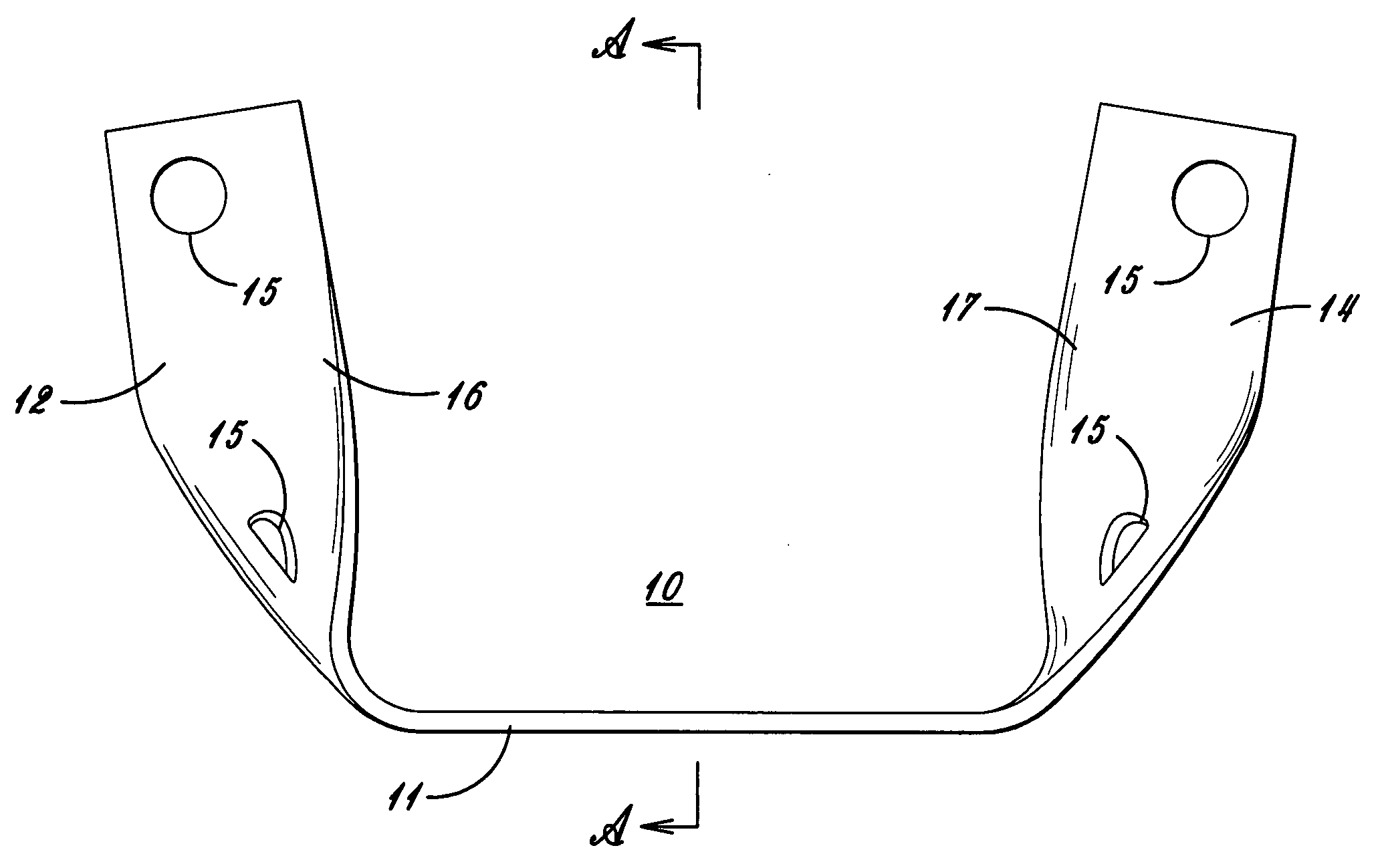
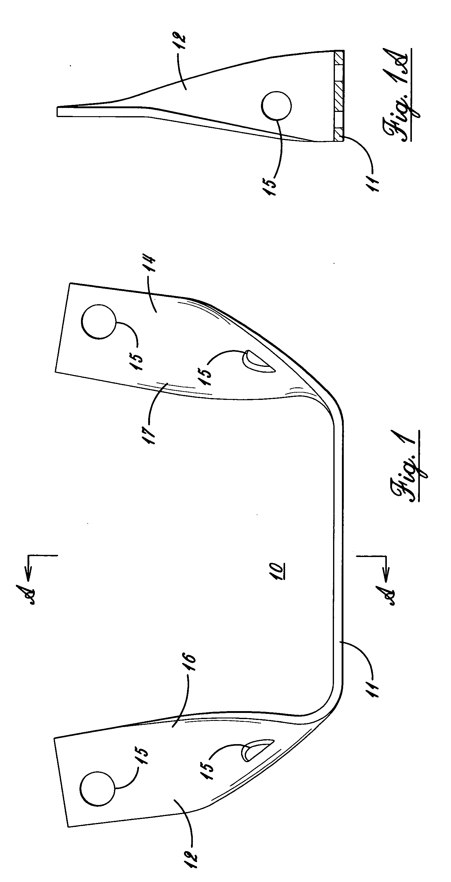
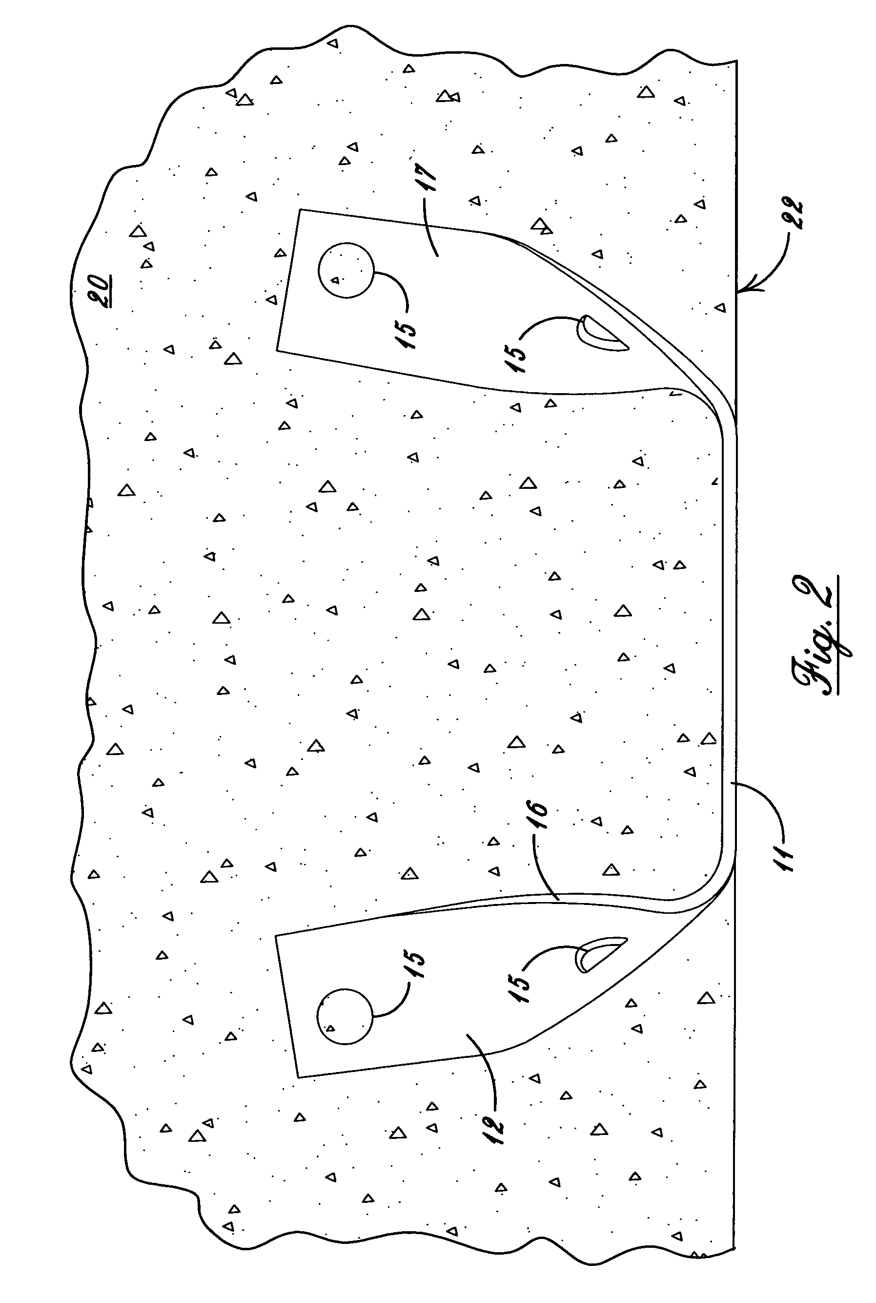
[0024] Preferring now more particularly to the drawings and FIGS. 1-4 thereof the connector 10 of the invention is therein illustrated. The connector 10 is of U shape, and includes a center flange 11 and two side flanges 12 and 14. The connector 10 is preferably formed by bending a flat strip of metal, preferably stainless steel, of two inch width, and one quarter inch thickness with an initial length of twenty inches. The side flanges are bent to an angle of 90°, six inches from the end of the strip, and the ends of the flanges are twisted at an angle of 90°; providing curved surfaces 16 and 17.

[0025] The side flanges 12 and 14 can be provided with two or more holes 15...


PUM


Abstract

Connectors for connecting preformed concrete panels, which connectors have doubletee flanges extending from a center flange, forming a U shape, with the flanges twisted at their ends an angle of 90 degrees from the center, forming a curved surface between the ends and the center flange, the connectors carried in and having the center flanges flush with the sides of the panels, each center flange meeting a like center flange in an adjoining panel, with the center flanges welded together to connect the concrete panels.

Description

BACKGROUND OF THE INVENTION [0001] 1. Field of the Invention [0002] This invention relates to a connector for connecting concrete panels, of the type which is formed from a strip of metal, which has a center flange and two side flanges perpendicular thereto, and bent from their ends at a ninety degree angle to form a U shaped connector, for insertion into a concrete panel and, which abuts a like connector in an adjoining panel with the center flanges welded together to connect the panels. [0003] 2. Description of the Prior Art [0004] Precast concrete panels are widely used in the construction industry to form the floor, walls or roof of buildings. These precast panels are usually formed offsite in a factory, where rebar is placed in a form and concrete is poured therein and left to harden. It is desirable to be able to accurately line up the panels for shear transfer between the panels. Typically weld plates or grout keys have been used to handle the shear transfer, which were embed...

Claims


Application Information

Patent Timeline
Patent Type & Authority Applications(United States)
IPC IPC(8): E04B1/38
CPCE04B1/41
Inventor SAMPLE, ALAN H.
Owner SAMPLE ALAN H
Why Eureka
Try Eureka