Directional resistivity antenna shield

a resistivity antenna and shield technology, applied in the direction of subaqueous/subterranean adaption, instruments, electromagnetic wave detection, etc., can solve the problems of destroying sensitive antenna components, lwd tools are routinely subject to severe mechanical impacts with the borehole wall and cuttings, and transmitting and receiving antennae that are capable, etc., to achieve low distortion, simple and inexpensive fabrication, and low attenuation

Inactive Publication Date: 2013-07-30
SCHLUMBERGER TECH CORP
View PDF54 Cites 6 Cited by
  • Summary
  • Abstract
  • Description
  • Claims
  • Application Information

AI Technical Summary

Benefits of technology

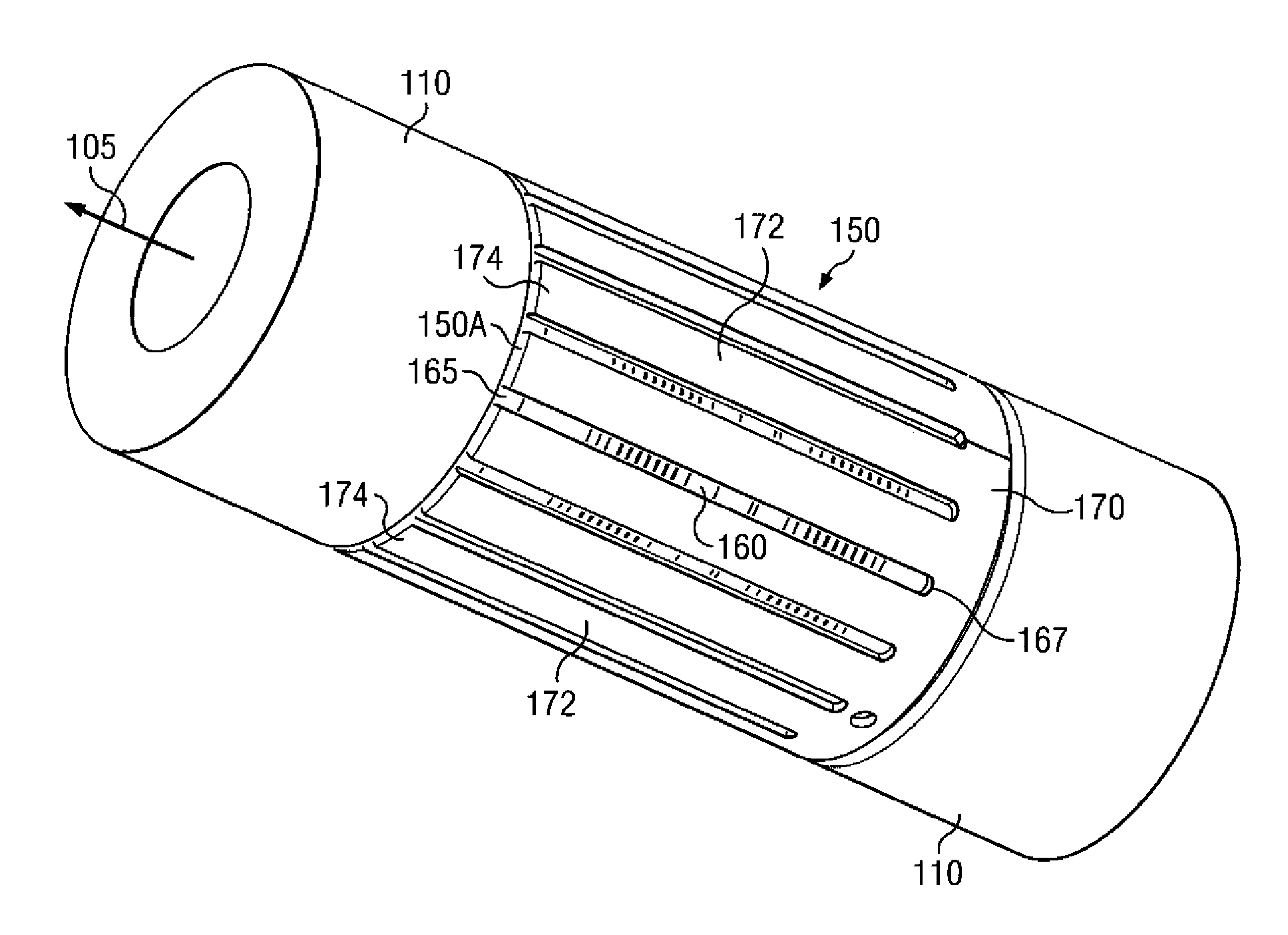
[0011]Exemplary embodiments of the present invention may advantageously provide several technical advantages. For example, antenna shields in accordance with the present invention have been found to provide suitable physical protection for sensitive antenna components while at the same time having a low attenuation to both z-mode and x-mode (and / or y-mode) electromagnetic waves. As such, shields in accordance with the present invention may be advantageously used for collocated, multi-mode antennae. Being essentially transparent to both z-mode and x-mode, the shields tend to impart little distortion to the transmitted and / or received electromagnetic waves. Moreover, the inventive shield does not require the use of sloped, curved, and / or circumferential slots. Preferred embodiments of the invention make use of axial slots having at least one electrically open end and therefore tend to provide for relatively simple and inexpensive fabrication.

Problems solved by technology

One difficulty in making LWD resistivity measurements (both conventional and directional measurements) is constructing transmitting and receiving antennae that are capable of withstanding the demanding downhole conditions.
As is known to those of ordinary skill in the art, LWD tools are routinely subject to severe mechanical impacts with the borehole wall and with cuttings in the borehole fluid.
These impacts would quickly destroy the sensitive antenna components if they were left unprotected.
There is a difficult practical tradeoff in configuring an antenna shield that provides sufficient mechanical protection and has a low, non-selective attenuation.
In general, highly protective shields tend also to be highly attenuating.
As such, the conventional wisdom in the art is that axially slotted shields are unsuitable for use with directional resistivity antennae (antennae that are configured to transmit and / or receive transverse mode or mixed mode electromagnetic waves).
These slots can compromise the structural integrity of the tool.
In addition, fabrication of drill collars having multiple sloped, curved, and / or circumferential slots typically requires complex and expensive machining operations.

Method used


Image

  • Directional resistivity antenna shield
  • Directional resistivity antenna shield
  • Directional resistivity antenna shield

Examples


Embodiment Construction

[0027]Referring now to FIGS. 1 through 8, exemplary embodiments of the present invention are depicted. With respect to FIGS. 1 through 8, it will be understood that features or aspects of the embodiments illustrated may be shown from various views. Where such features or aspects are common to particular views, they are labeled using the same reference numeral. Thus, a feature or aspect labeled with a particular reference numeral on one view in FIGS. 1 through 8 may be described herein with respect to that reference numeral shown on other views.

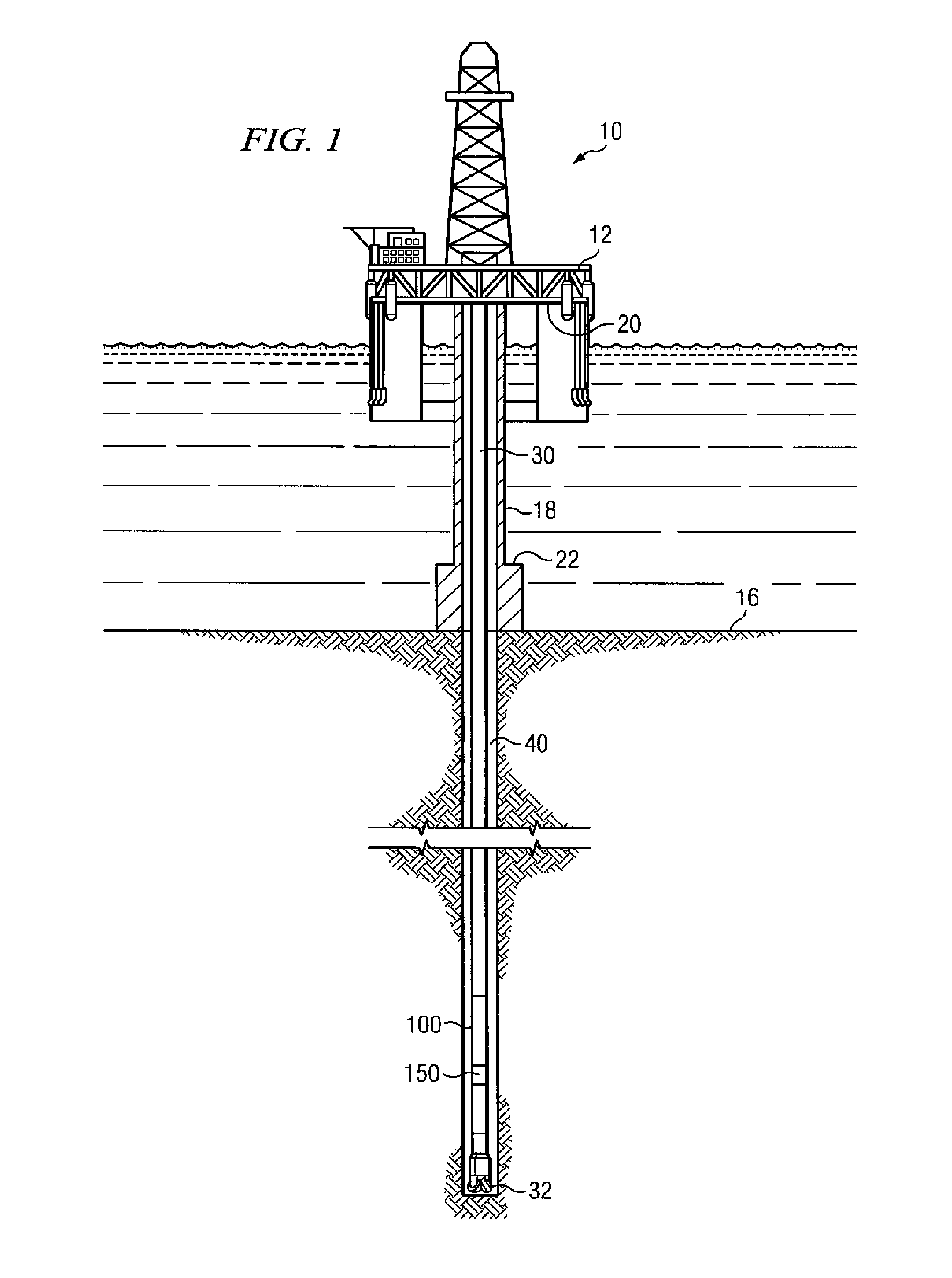
[0028]FIG. 1 depicts one exemplary embodiment of a logging while drilling tool 100 in use in an offshore oil or gas drilling assembly, generally denoted 10. In FIG. 1, a semisubmersible drilling platform 12 is positioned over an oil or gas formation (not shown) disposed below the sea floor 16. A subsea conduit 18 extends from deck 20 of platform 12 to a wellhead installation 22. The platform may include a derrick and a hoisting apparatus for r...


PUM


Abstract

A logging while drilling tool includes a directional resistivity antenna and an antenna shield having. The shield has at least one slot having at least one electrically open end formed therein. The antenna shield may include a base portion and a plurality of spaced apart fingers extending away from the base portion such that the finger ends are electrically isolated from the tool body and from one another. The antenna shield may alternatively include a plurality of spaced apart plates that are electrically isolated from the tool body and from one another. These antenna shields have been found to provide suitable physical protection for sensitive antenna components while at the same time being substantially transparent to both z-mode and x-mode electromagnetic waves.

Description

RELATED APPLICATIONS[0001]None.FIELD OF THE INVENTION[0002]The present invention relates generally to downhole measurement tools utilized for measuring electromagnetic properties of a subterranean borehole. More particularly, embodiments of this invention relate to an antenna shield configured for use with a directional resistivity antenna.BACKGROUND OF THE INVENTION[0003]The use of electrical measurements in prior art downhole applications, such as logging while drilling (LWD), measurement while drilling (MWD), and wireline logging applications is well known. Such techniques may be utilized to determine a subterranean formation resistivity, which, along with formation porosity measurements, is often used to indicate the presence of hydrocarbons in the formation. For example, it is known in the art that porous formations having a high electrical resistivity often contain hydrocarbons, such as crude oil, while porous formations having a low electrical resistivity are often water satu...

Claims


Application Information

Patent Timeline
Patent Type & Authority Patents(United States)
IPC IPC(8): G01P3/48G01P3/54
CPCG01V3/30G01V3/28
Inventor WANG, TSILIZHANG, JUNLI, JINGBONNER, STEPHEN D
Owner SCHLUMBERGER TECH CORP
Why Eureka
Try Eureka