
Microdevices for chemical sensing and chemical actuation

a micro-device and sensor technology, applied in the field of chemical sensing and chemical actuation sensors, can solve the problems of limiting both sensitivity and current devices, moving laborious and time-intensive steps, and other inorganic materials, and achieve the effect of high resolution

Inactive Publication Date: 2013-01-01
UNIV OF VIRGINIA ALUMNI PATENTS FOUND
View PDF102 Cites 3 Cited by
  • Summary
  • Abstract
  • Description
  • Claims
  • Application Information

AI Technical Summary

Benefits of technology

The invention is a portable device that uses polymeric materials to detect molecules with high precision using a technique called μ-TAS. The device is stable and sensitive, and can detect small amounts of analytes without the need for external hardware. The unique design allows for the detection of adsorption through a process of mechanical bifurcation, which can be used to create micro-valves that respond to adsorption and enable chemically-actuated control features. Overall, the invention offers improved portability, sensitivity, and simplicity in integration into existing μ-TAS.

Problems solved by technology

While the microchip revolution is rooted in ultra fast separations, recent forays seek to move laborious and time-intensive steps for sample chemical and biological identification to microchips.
One of the important issues for proper function of a μ-TAS is the ability to detect a wide variety of chemical and biological analytes, such as ions, drugs, DNA and proteins.
Although such chemo-mechanical sensor concepts have proven their utility, current devices are limited by to several disadvantages.
First, the use of silicon (or other inorganic materials) limits both sensitivity (due to the large stiffness of such materials) and robustness (due to the small failure strains and brittle nature of such materials) of such devices.
The stiffness of these materials is particularly problematic; adsorption typically induces cantilever deflections on the order of 10-100 nm (Lavrik et al., Review of Scientific Instruments 75:2229-2253, 2004; Lang et al., Materials Today, April, 30-36, 2005), which requires sophisticated laser-based detection hardware.
Second, prior art cantilevers are stand alone detectors that are not incorporated into an integrated μ-TAS, possibly due to the required sophisticated detection system that cannot be integrated directly into a μ-TAS.

Method used


Image

  • Microdevices for chemical sensing and chemical actuation
  • Microdevices for chemical sensing and chemical actuation
  • Microdevices for chemical sensing and chemical actuation

Examples


Embodiment Construction

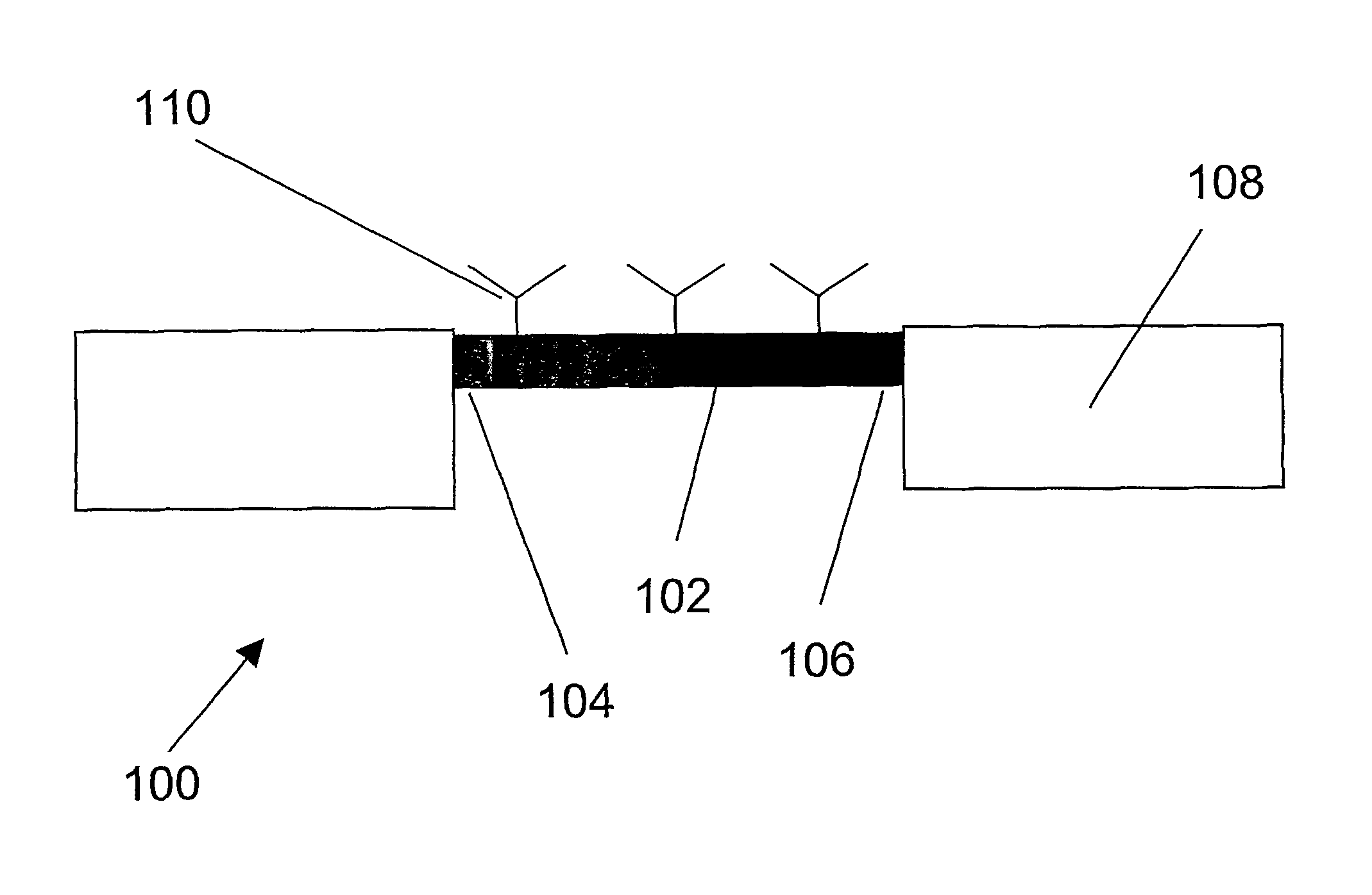
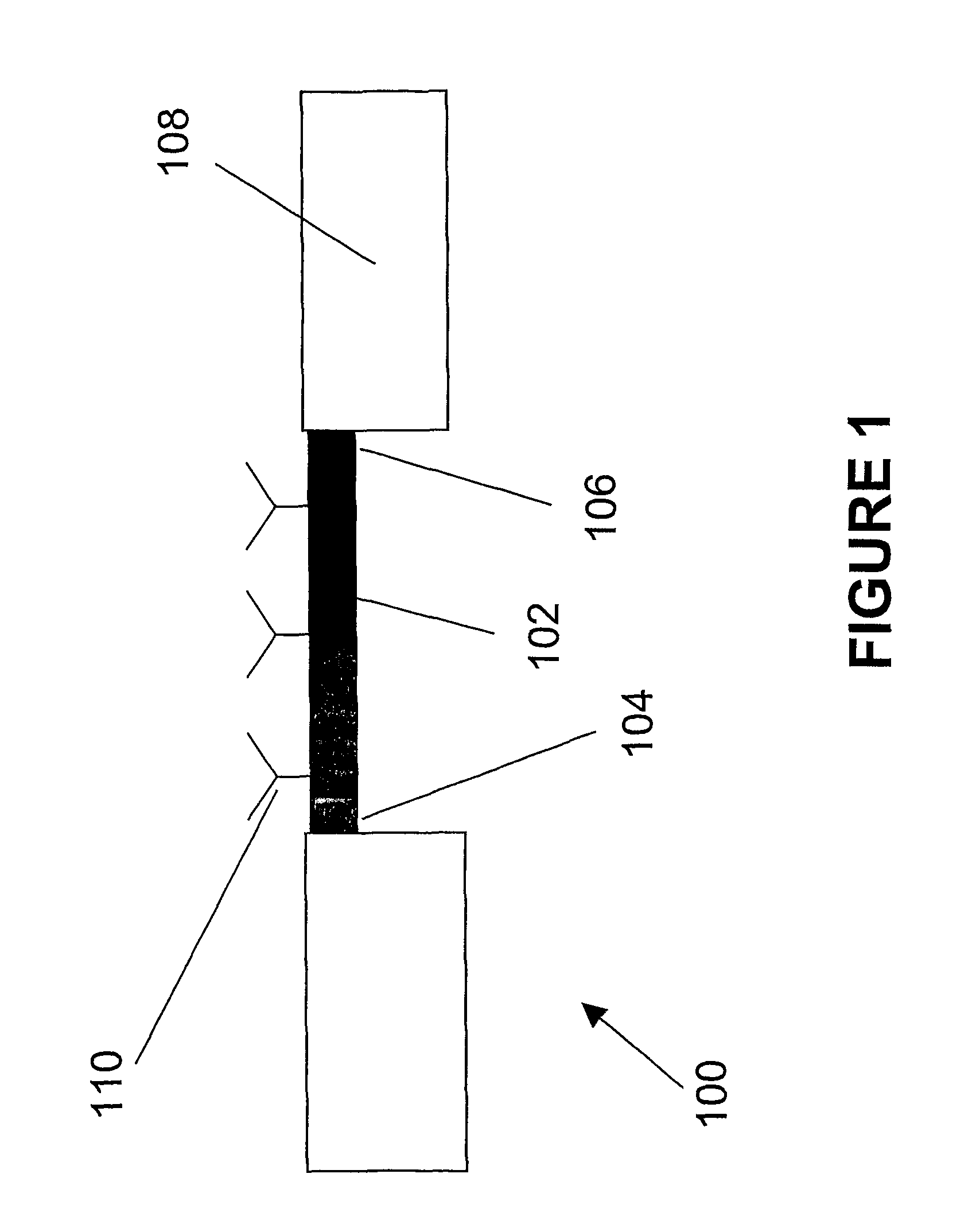
[0035]A schematic diagram of the present sensor 100 is depicted in FIG. 1. The sensor 100 contains a membrane 102 that is clamped to a platform 108 at least at two ends 104, 106 or around part of or the entire periphery of the membrane. To facilitate specific binding to the analyte, the surface or surfaces of the membrane 102 may be derivatized with a binding member 110 of a binding pair, such as antibody / antigen or complimentary nucleic acids. Although FIG. 1 shows one surface of the membrane 102 being derivatized with a binding member, the other side or both surfaces may contain the binding member depending on which side of the membrane comes in contact with the analyte. If both sides of the membrane 102 come in contact with the analyte, both sides may contain the binding member.

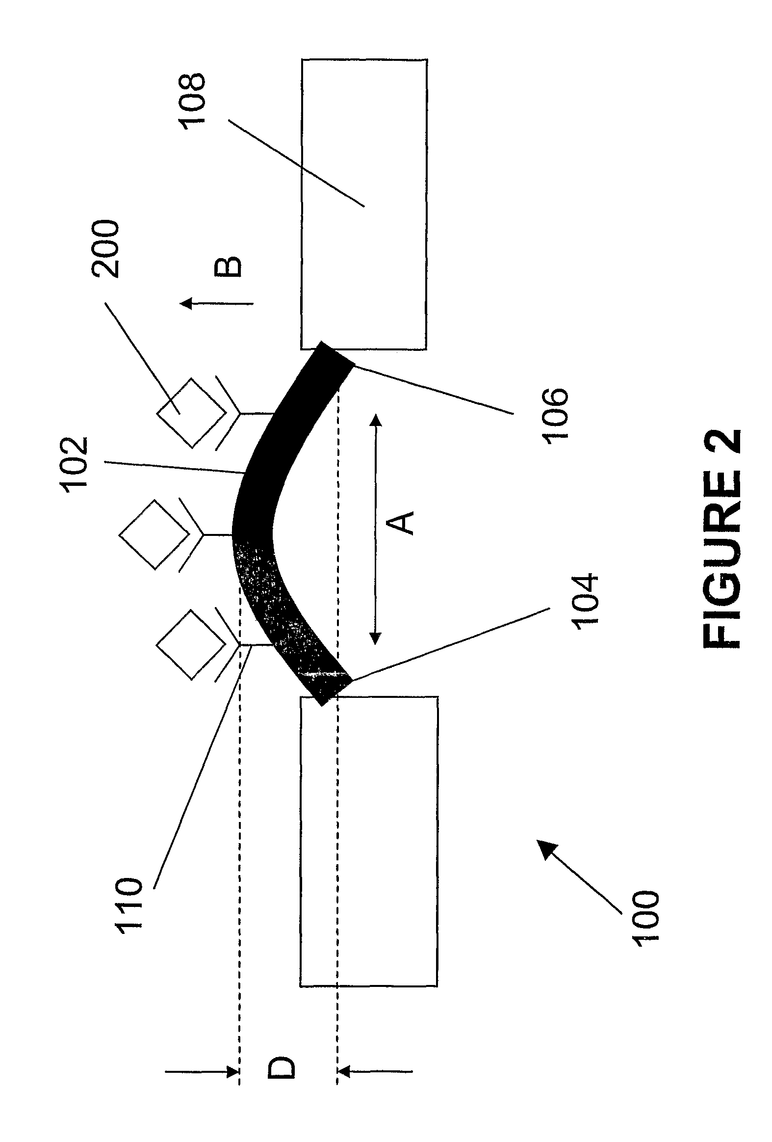
[0036]As shown in FIG. 2, when the analyte 200 binds to the binding member 110, the membrane 102 deform out-of-plane by distance D. This deformation is caused by the surface stress in direction A, that ten...


PUM

PropertyMeasurementUnit
diameteraaaaaaaaaa
temperatureaaaaaaaaaa
physical changeaaaaaaaaaa

Abstract

The invention relates to sensors for detecting chemical and biological material and for chemical actuation. In particular, the sensors of the present invention incorporates membranes or beams that are deformable in the presence of chemical adsorption on its surface. The sensor of the present invention contains a polymeric membrane or beam (102) that is clamped at least at two opposing ends (104) and (106).

Description

[0001]This application claims priority of U.S. Provisional Patent Application Nos. 60 / 704,274, filed Aug. 1, 2005, and 60 / 774,293, filed Feb. 16, 2006, which are incorporated herein by reference.FIELD OF THE INVENTION[0002]The invention relates to sensors for detecting chemical and biological material and for chemical actuation. In particular, the sensors of the present invention incorporates membranes or beams that are deformable in the presence of chemical adsorption on its surface.BACKGROUND OF THE INVENTION[0003]The advent of microdevice technology for biochemical and chemical analysis has begun to revolutionize the world of science. While the microchip revolution is rooted in ultra fast separations, recent forays seek to move laborious and time-intensive steps for sample chemical and biological identification to microchips. Success with these developments will supplant the use of multiple instruments in the laboratory with the cost-effectiveness and rapid response of using a si...

Claims


Application Information

Patent Timeline
Patent Type & Authority Patents(United States)
IPC IPC(8): C12M1/34
CPCF16K99/0001F16K99/0015F16K99/0034B01L3/5027B01L7/52F16K2099/0074F16K2099/0078F16K2099/0084
Inventor BEGLEY, MATTHEW R.LANDERS, JAMES P.FERRANCE, JEROME P.HUANG, LINGJONES, MICHAEL H.UTZ, MARCELBARKER, SCOTT
Owner UNIV OF VIRGINIA ALUMNI PATENTS FOUND
Learn More