
Tool for removing dents from sheet metal

a technology for removing dents and sheet metal, which is applied in the field of tools for pulling dents, can solve the problems of affecting the removal effect of dents, the risk of breaking or disconnection of the coupling device from the sheet metal surface, etc., and achieves the effect of easy and accurate removal of dented portions

Inactive Publication Date: 2007-03-15
KNOWLES STEVEN MICHAEL
View PDF0 Cites 8 Cited by
  • Summary
  • Abstract
  • Description
  • Claims
  • Application Information

AI Technical Summary

Benefits of technology

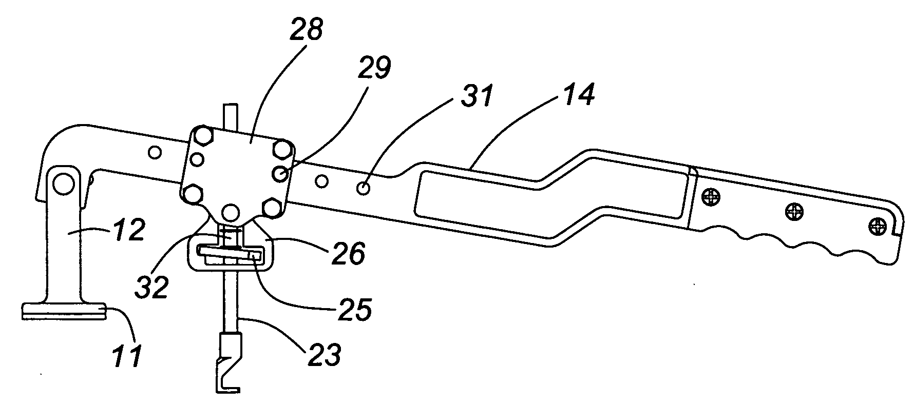
[0013] In operation, the lever arm is displaced about the pivoting point on the support post by only a limiting range of movement, preferably moving the link carrying the pulling rod pivot joint only + / −10 degrees above or below the common plane referenced above. With this arrangement the movement of the pulling rod and its pivoting joint during use remains virtually vertical, minimizing any sidewards force to be applied to the sheet metal connector. Within the range + / −10 degrees these elements are displaced only very slightly sideways. Beyond this range there develops an increasingly sideways motion and a sideways twisting force. The pivoting joint in the pulling rod helps compensate for even this minute movement by minimizing the application of shear forces to the sheet metal connector.
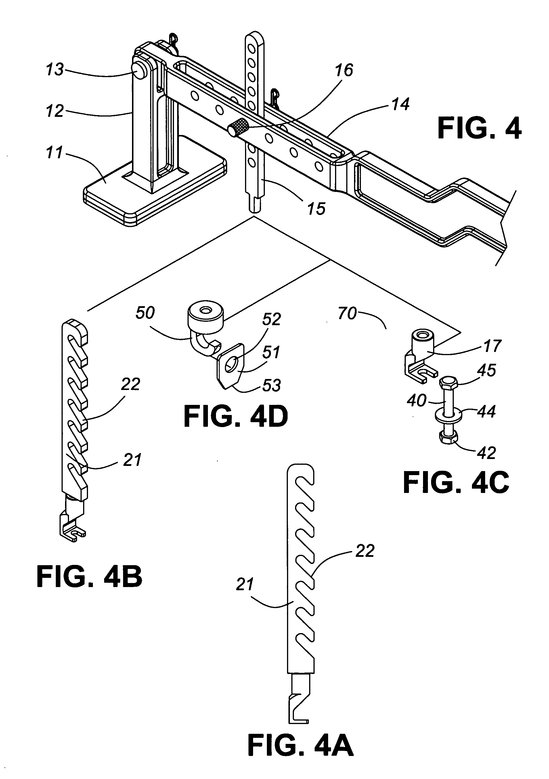
[0016] While this ratcheting effect is very desirable in terms of maximizing the lever advantage of the tool and minimizing the application of sidewards force to the sheet metal coupling, the use of a undulating or indented coupling edge on the pulling rod “granularizes” the adjustment that is available to be made between each stroke. As a further feature of the invention, a continually adjustable coupling between the lever arm and the pulling rod may be provided.
[0020] Additionally, this improved threaded engagement post may be provided with a drilling tip that initiates penetration of the threaded portion of the post into engagement with the sheet metal. A self-tapping thread is positioned on the engagement post directly behind the drilling tip. Formation of an initial opening in the sheet metal by the drilling tip facilitates subsequent engagement of the self-tapping thread in the hole formed in the sheet metal.
[0023] A further fastening system is based upon the use of a welding tab having an opening in the tab which may be engaged by a, preferably, single-hooked coupling mean. This welding tab may be in the form of a preferably flat plate of metal which may be stamped to form an opening and provide a short, straight, lower edge. The edge is for welding to the sheet metal which is to be straightened. Because it is an edge with a definite length, e.g. 5 to 10 mm, it may more easily be welded to the sheet of steel than the standard pins that are used in the industry. Further, a stronger bond with the sheet metal is created by the length of this weld.
[0025] Individually, the various features of the invention constitute useful advances in the art of tools used in the bodywork industry. By the combination of these features a new and superior tool is provided to permit the easy and accurate removal of dented portions from the sheet metal surfaces.

Problems solved by technology

Any tendency to twist the coupling device will risk a breakage or its disconnection from the sheet metal surface.

Method used


Image

  • Tool for removing dents from sheet metal
  • Tool for removing dents from sheet metal
  • Tool for removing dents from sheet metal

Examples


Embodiment Construction

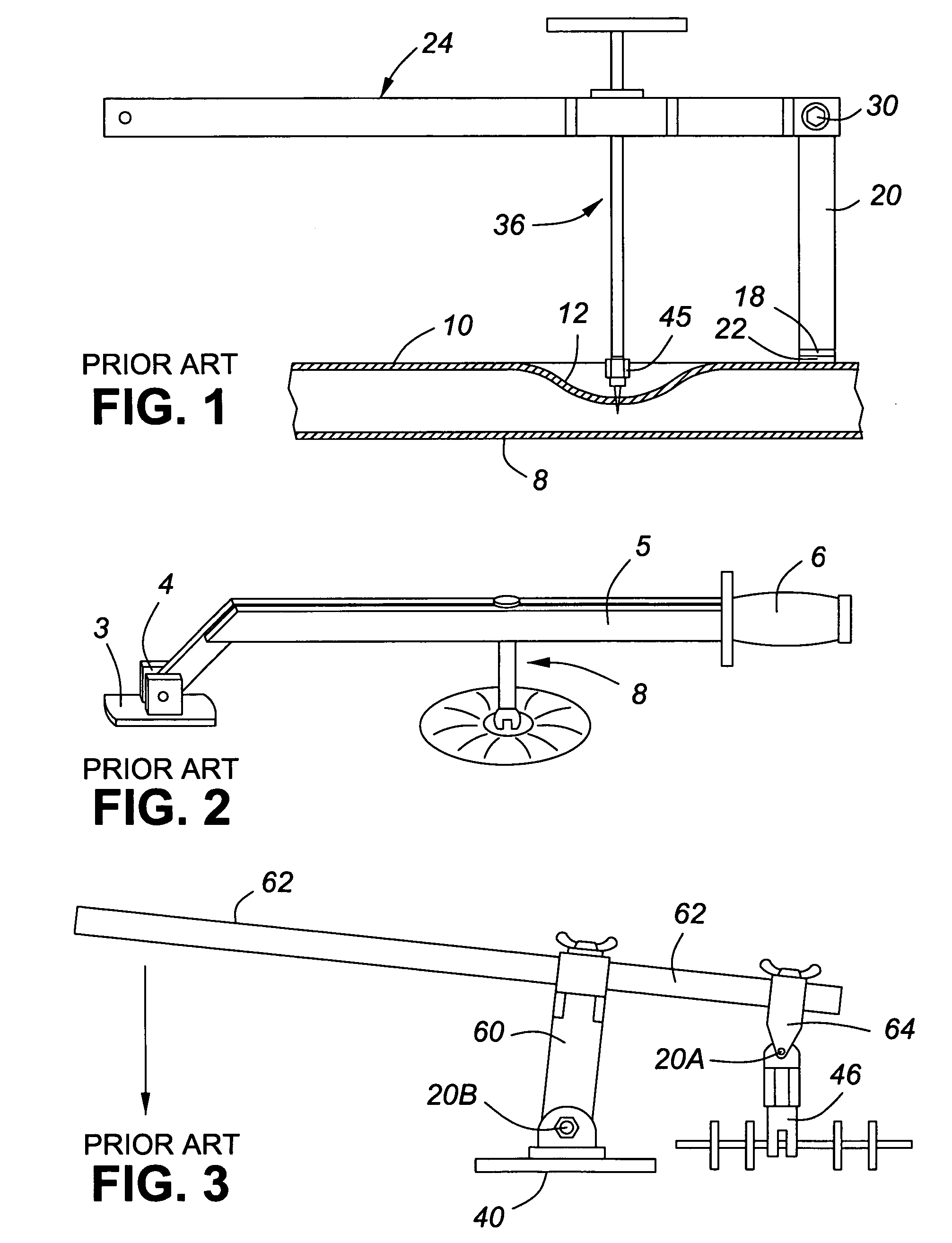
[0040]FIG. 1 shows the prior art metal panel repair tool U.S. Pat. No. 2,749,795, dated Jun. 12, 1956 issued to Boykin, Jr. This device provides a support post 20 with a base 18 shaped to rest against an adjacent portion of an outer body panel 10 overlying an inner body panel 8 on a vehicle. To this post 20 is connected a hinged lever arm 24 with an extending handle portion which, in turn, carries a connecting or pulling rod 36 for coupling to the dented portion 12 of the surface 10 which is to be drawn-out. This mechanism acts as a second lever.

[0041] The pulling rod 36 is fastened to a sheet metal screw 45 which engages with the inwardly-dented sheet metal surface 10. The lever arm 24 and support post 20 are depicted as being at 90° to each other at the commencement of the pulling process. In this configuration the pulling rod 36 is parallel to the upright support post 20 which extends vertically from the auto body surface 10. No provision is made for the pulling rod 36 to swivel...


PUM

PropertyMeasurementUnit
lengthaaaaaaaaaa
of rotationaaaaaaaaaa
rotationaaaaaaaaaa

Abstract

A tool for pulling a dent out of a sheet metal surface has a support post with a foot shaped to rest against a portion of the sheet metal surface adjacent the dent. The tool includes a hinged lever arm which is pivotally connected to this support post at a lever arm pivot point which is elevated above the foot and adjacent sheet metal region. The tool also includes a pulling rod for coupling, through a fastener or connecting means, to the dented portion of the surface which is to be drawn-out, the pulling rod being connected to the hinged lever arm through a pivoting joint. The pivoting joint of the pulling rod and the lever arm pivoting point are positionable through actuation of the lever arm able to lie in a common plane which is substantially parallel to the sheet metal surface into which the dent is to be drawn into alignment. The pulling rod is adjustable in its engagement with the lever arm to permit the lever arm to swing through a limited angular range. Coupling between the pulling rod and lever arm is either discrete or continuous. Fasting means connecting the tool to the sheet metal include a self-tapping, self-drilling screw or a bolt provided with a magnetic washer or magnetic head.

Description

FIELD OF THE INVENTION [0001] This invention relates to a tool for pulling dents, amongst other applications, from the sheet metal portions of an auto body in the process of auto-body repairing and refinishing. More particularly, the invention relates to a hand-operated pulling device with an improved system for connecting to and applying force to the surface which is to be pulled. BACKGROUND TO THE INVENTION [0002] Various devices have been proposed to allow an auto-body repairman to apply an outward force to an inwardly dented surface, restoring the surface to close to its original profile. One example is U.S. Pat. No. 2,749,795, dated Jun. 12, 1956 issued to Boykin, Jr. (FIG. 1 hereafter). This device provides a support post with a foot shaped to rest against an adjacent portion of a body panel on a vehicle. To this post is connected, at a height above the panel, a hinged lever arm with a handle which, in turn, carries a connecting rod for coupling to the dented portion of the su...

Claims


Application Information

Patent Timeline
Patent Type & Authority Applications(United States)
IPC IPC(8): B21D1/12
CPCB21D1/06
Inventor KNOWLES, STEVEN MICHAEL
Owner KNOWLES STEVEN MICHAEL
Learn More