Method and apparatus for sampling a fluid

a fluid and fluid technology, applied in the field of fluid sampling, can solve the problems of complex disclosed sampling devices, distortion of the accuracy of ‘true’ sample reading, and inability to address lauks problems associated with problems, and achieve the effect of facilitating the sample volume carrying portion

Inactive Publication Date: 2007-03-15
INVETECH
View PDF29 Cites 15 Cited by
  • Summary
  • Abstract
  • Description
  • Claims
  • Application Information

AI Technical Summary

Benefits of technology

[0022] In accordance with embodiments of the present invention, a reservoir integral to the piercing needle provides advantages over complex related art mechanisms, which do not facilitate a sample volume carrying portion. Embodiments of the present invention enable a fluid sampling system to hold a volume of fluid with the envelope of a disposable piercing tip. It is desirable, with this functionality at hand, to be able to pick up disposable tips in the form of probes according to embodiments of the invention, pierce and aspirate from closed containers and carry the sampled fluid around dispensing possibly to a number of locations, within a laboratory or laboratory instrument for example, from the sample fluid reservoir. There are a number of applications for the present invention in industry. One example, without being a limiting example, is the enablement by use of the invention of a high throughput aliquotting system for handling precise quantities of material. Accordingly, the division of a sample of a substance into equal parts, each of which representing a known quantitative relationship to each other and to the sample as a whole is enabled on a large scale.

Problems solved by technology

Piercing the bung, or cap, has many problems associated with it in the related art.
Manually, or otherwise removing caps prior to insertion into the instrument exposes the user to contamination by the sample, and further exposes the environment and the sample to contamination, as well as allowing evaporation of the sample to occur which may distort the accuracy of the ‘true’ sample reading.
The disclosed sampling device is complex and includes an adapting element for fitting the test tube with, a piercing needle first to a separate sampling device, a cup-like sample receptacle and a suction device fitted in connection to the receptacle for drawing sample from the test tube into the sample receptacle.
Lauks does not address the problems associated with efficient and high volume handling of fluid samples in an automated system.

Method used


Image

  • Method and apparatus for sampling a fluid
  • Method and apparatus for sampling a fluid
  • Method and apparatus for sampling a fluid

Examples


Embodiment Construction

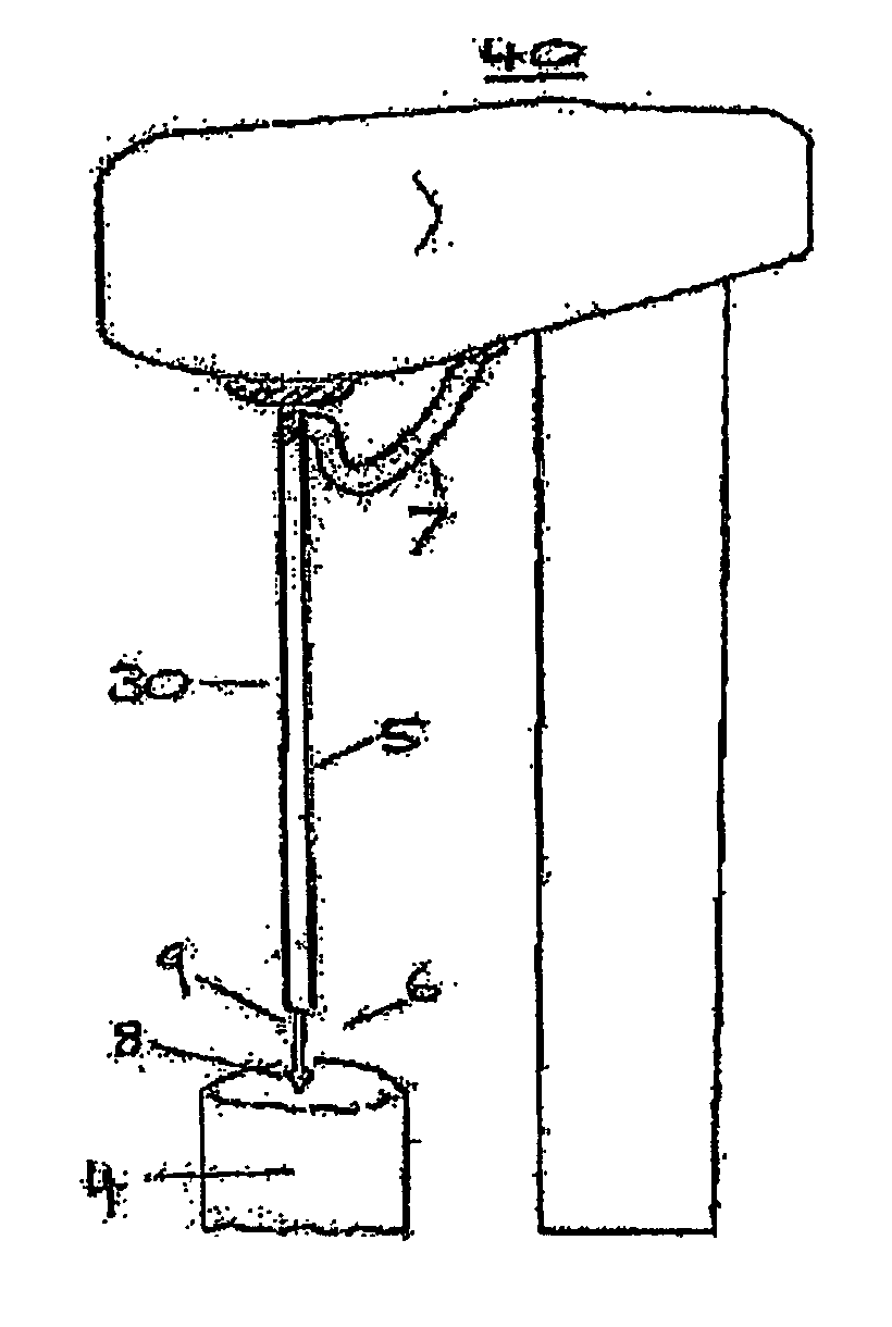
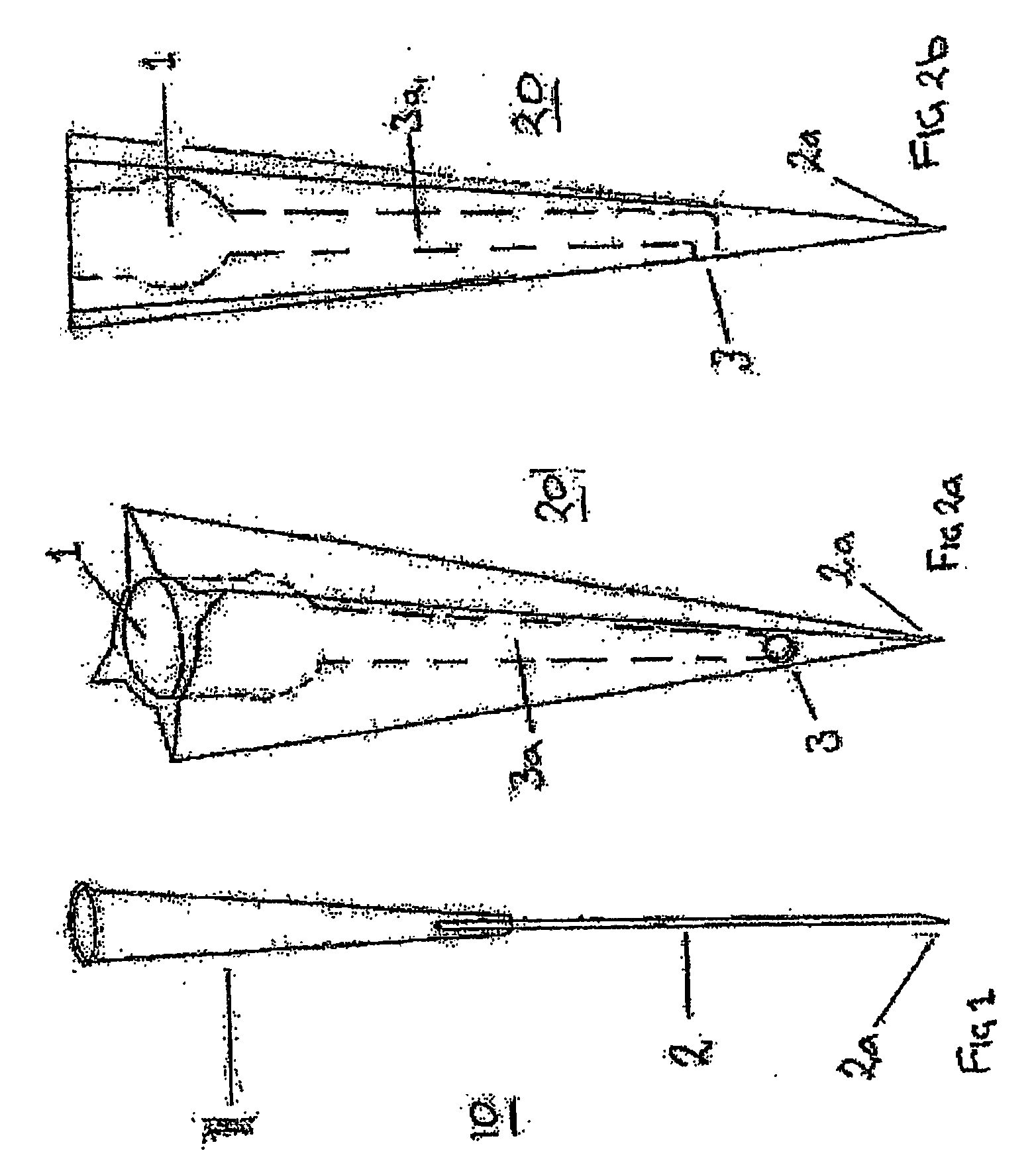
[0035]FIG. 1 shows a first embodiment of a fluid sampling probe 10 comprising a moulded fluid receiving region in the form of a reservoir 1. The probe 10 may be in the form of a range of reservoirs of different volumes with a hypodermic needle 2 attached to the reservoir 1. The fluid reservoir 1 may accommodate a volume of fluid and the needle head 2a may penetrate a bung / cap of a closed fluid carrier (not shown) to the depth required. The preferred form of fluid carrier for which the present invention has application may be a Vacutainer™, a common form of vial for containing biological fluid. The small diameter needle head 2a requires minimal force to pierce the bung / cap. The assembly 10 is disposable for dedicated use on each sample contained in a fluid carrier. Generally, the assembly 10 incorporates a metal needle 2 for piercing and a moulded reservoir 1 to contain the sample volume. The fluid sampling probe 10 is typically attached to a fluid sampling system by pressing the flu...


PUM

PropertyMeasurementUnit
volumeaaaaaaaaaa
diameteraaaaaaaaaa
sizesaaaaaaaaaa

Abstract

A fluid sampling probe may be provided in a unitary assembly for aspirating fluid samples by way of a reduced diameter piercing portion in direct fluid communication with a reservoir for (temporarily) storing and/or transporting a sample, including: a first portion for piercing a closed fluid carrier, a second portion serving as a reservoir for receiving a fluid, the second portion being formed integrally operative with the first portion and a third portion providing fluid communication between the first and second portion. The fluid sampling probe 20 may be used to provide a high throughput aliquotting system for handling precise quantities of material. Accordingly, the division of a sample of a substance into parts (equal or otherwise), each of which representing a known quantitative relationship to each other and to the sample as a whole is enabled on a large scale.

Description

RELATED APPLICATIONS [0001] This application claims priority to Australian Provisional Patent Application No. 2003903254, filed 27 Jun. 2003 by the present applicant and entitled “Method and Apparatus for Sampling a Fluid” and, the specification thereof is incorporated herein by reference in its entirety and for all purposes. FIELD OF INVENTION [0002] The present invention relates to the field of fluid sampling, including a method, apparatus and / or system therefor, for example, the invention relates to aspirating fluid samples from closed containers. In one form, the invention relates to a method and apparatus for aspirating fluid samples from Vacutainers™ or vials containing biological fluid, and it will be convenient to hereinafter describe the invention in relation to that application. It should be appreciated, however, that the present invention is not limited to that application, only. In one particular aspect, the present invention is also suitable for use in providing an auto...

Claims


Application Information

Patent Timeline
Patent Type & Authority Applications(United States)
IPC IPC(8): G01N1/00A61J1/20B01L3/02G01N35/10
CPCB01L3/0275B01L2200/026B01L2200/141G01N35/1079B01L2300/0838B01L2400/0406B01L2400/0487B01L2300/0672
Inventor GRANT, RICHARD ALEXANDERHANCOCK, WARREN JAMES
Owner INVETECH
Why Eureka
Try Eureka