Hydraulic relief valve
- Summary
- Abstract
- Description
- Claims
- Application Information
AI Technical Summary
Benefits of technology
Problems solved by technology
Method used
Image

Examples
Embodiment Construction
[0028] Hereinafter, a preferred embodiment of the present invention will be described with reference to the accompanying drawings. The matters defined in the description, such as the detailed construction and elements, are nothing but specific details provided to assist those of ordinary skill in the art in a comprehensive understanding of the invention, and thus the present invention is not limited thereto.
[0029] The construction of a hydraulic relief valve according to the present invention will now be described in detail with reference to the preferred embodiment.
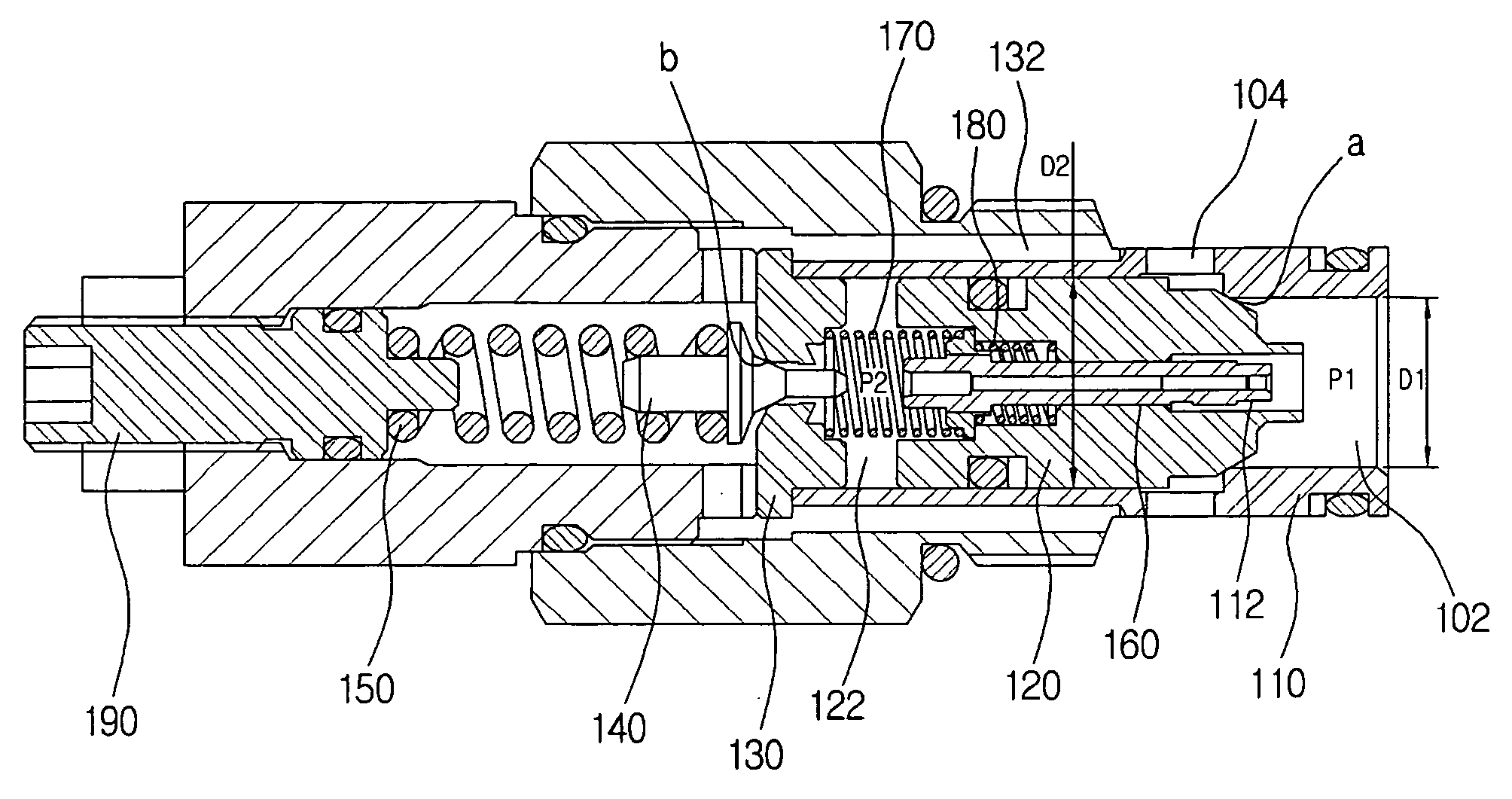
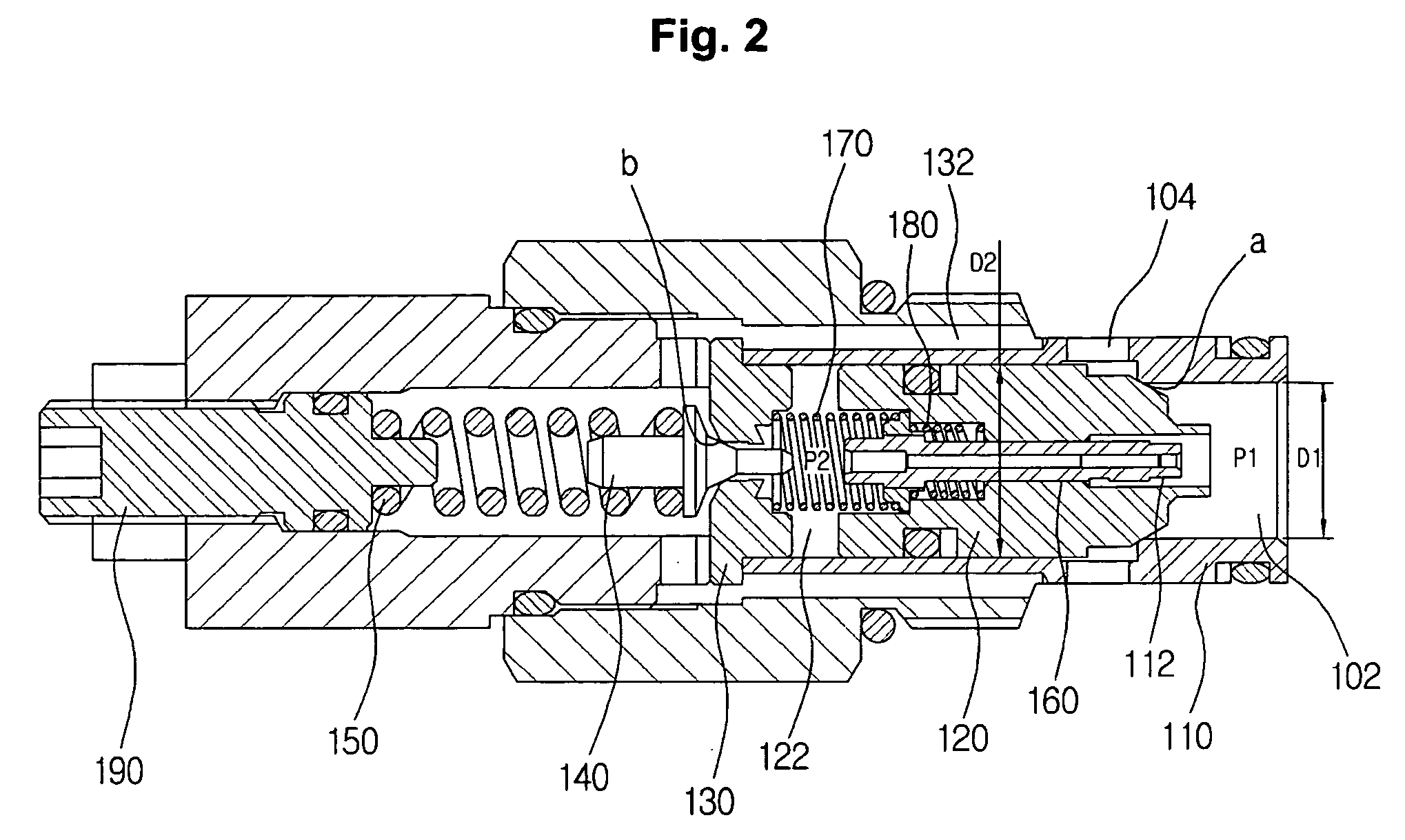
[0030]FIG. 2 is a cross-sectional view illustrating the construction of the hydraulic relief valve according to the present invention.
[0031] Referring to FIG. 2, the hydraulic relief valve includes a sleeve 110 having a high-pressure flow path 102 formed on one side of the sleeve, through which a hydraulic fluid of high pressure P1 passes from a hydraulic pump P, and a tank-side flow path 104 formed on an external sur...
PUM
 Abstract
Description
Claims
Application Information
 - Generate Ideas
- Intellectual Property
- Life Sciences
- Materials
- Tech Scout
- Unparalleled Data Quality
- Higher Quality Content
- 60% Fewer Hallucinations
Browse by: Latest US Patents, China's latest patents, Technical Efficacy Thesaurus, Application Domain, Technology Topic, Popular Technical Reports.
© 2025 PatSnap. All rights reserved.Legal|Privacy policy|Modern Slavery Act Transparency Statement|Sitemap|About US| Contact US: help@patsnap.com