Setting tool

a technology of setting tool and setting piston, which is applied in the direction of vibration dampers, manufacturing tools, mechanical equipment, etc., can solve the problems of undesirable second blows with the setting piston, increased weight damage to the essential and expensive tool components, so as to prevent the rebound of the setting tool, improve the return characteristics of the particles, and improve the mechanical properties

Active Publication Date: 2007-03-15
HILTI AG
View PDF30 Cites 9 Cited by
  • Summary
  • Abstract
  • Description
  • Claims
  • Application Information

AI Technical Summary

Benefits of technology

[0015] With the first ring and the second ring being supported against each other by an elastic element, e.g., a spring or a rubber element, the return of the first ring to its initial position away from the second ring and expansion of the receiving space after impact by the setting piston is insured in a simple manner.
[0016] It is advantageous when the elastic element is formed by an elastic annular body arranged between the first ring and the second ring and closing the receiving space radially outwardly. With such annular body, not only return of the rings to their initial position and expansion of the receiving space is achieved, but also sealing of the receiving space is insured. The sealing of the receiving space prevents exit of the particles radially outwardly. Further, the particles are displaced in the direction of the annular body under pressure, which positively influences the displacement between the first and second rings.
[0017] Advantageously, the particles have a size from 0.1 mm to 5.0 mm. When the particles are formed as balls, the size of the particles corresponds to the diameter of the balls. The ball-shaped particles prevent the rebound of the setting tool particularly good.
[0018] It is advantageous when the particles are surrounded circumferentially with a lubricant such as, e.g., oil or graphite. The lubricant improves the return characteristics of the particles.
[0019] Advantageously, the particles are formed as steel balls with a hardness of 40-65 HRC. Such particles have good mechanical properties and a long service life. However, other metal, ceramics or other suitable minerals can be used.
[0020] With the conical limiting surfaces having each the same cone half-angle in a range from 10° to 50°, advantageously, a good distribution of pressure, which is applied to the particles, is achieved.

Problems solved by technology

The drawback of the known setting tool consists in that when the wear of the elastic annular member is too large and the wear is not recognized, essential and expensive tool components can be damaged.
This increases the weight of the setting tool.
On the other hand, because of the elasticity of the annular member, the setting piston rebounds after impacting the annular member, and this leads, in particular at a high setting energy, to undesirable second blows with the setting piston.
However, in the setting tool of the German patent, the other drawback of DE 39 30 592 A1, namely, rebound of the setting piston, leading to secondary blows, remains.
The setting tool of the U.S. patent has the same drawback as the setting tool of the German patent.
Here, likewise, possible rebounds of the setting piston can lead to the secondary blows.

Method used


Image

  • Setting tool
  • Setting tool
  • Setting tool

Examples


Embodiment Construction

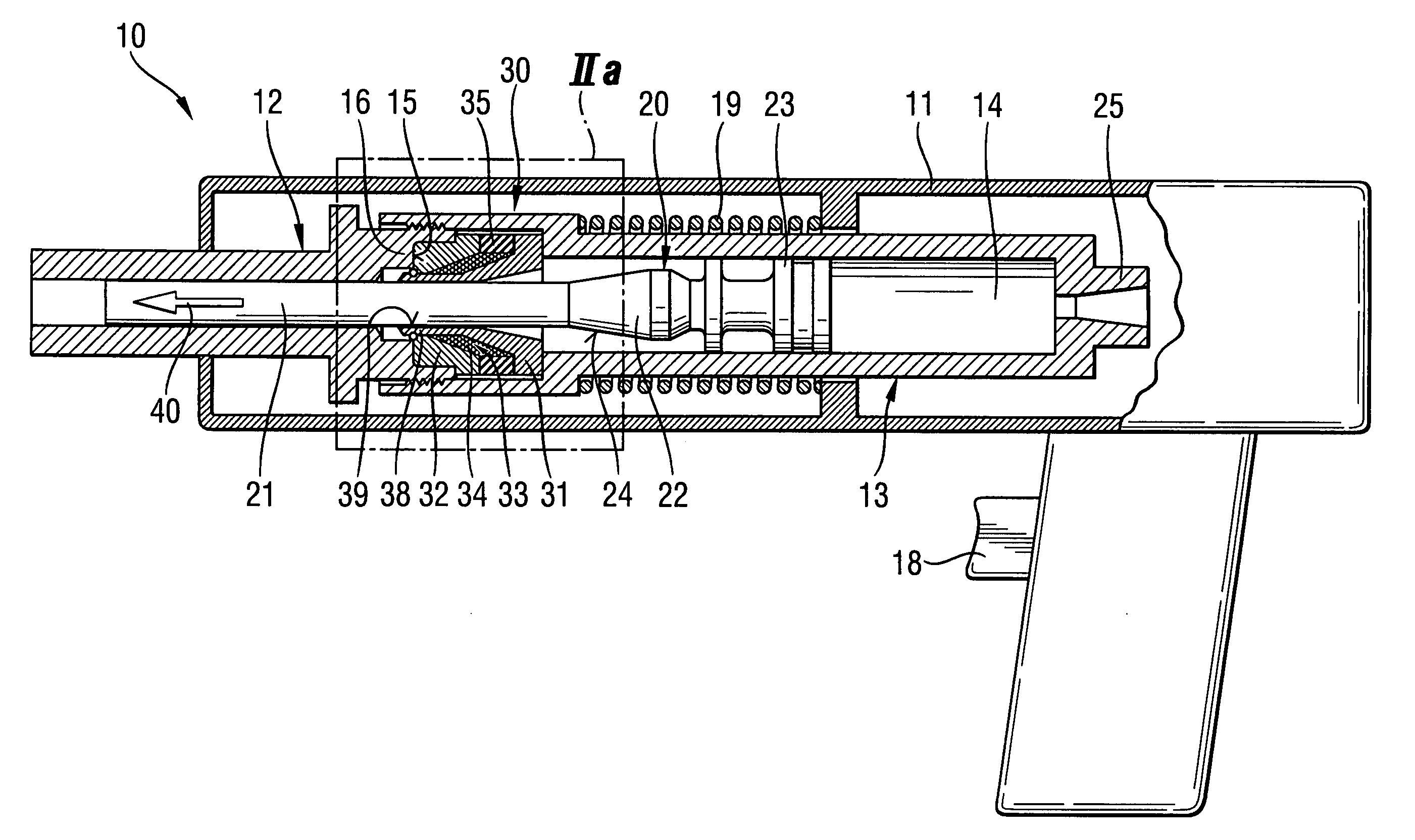
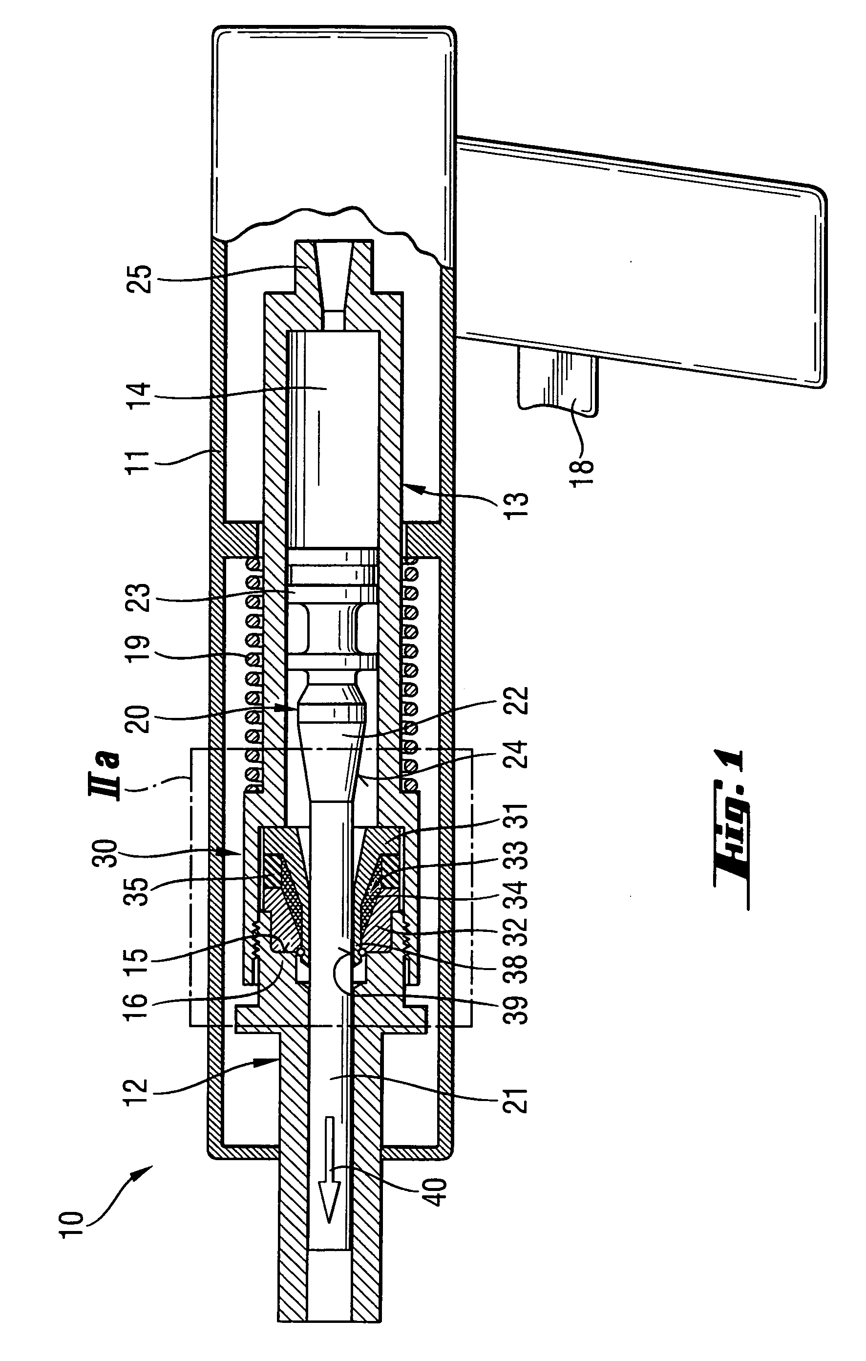
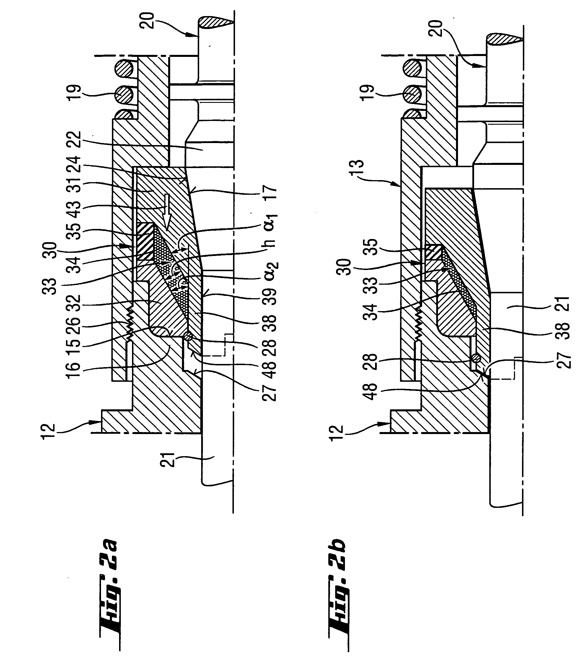
[0030] A setting tool 10 according to the present invention, which is shown in FIGS. 1-2a, has a piston stop device generally designated with a reference numeral 30. The setting tool 10 further includes a one- or multi-piece housing 11 and a piston guide 13 arranged in the housing 11. In the hollow chamber 14 of the piston guide 13, a setting piston 20 is displaceably arranged. The setting piston 20 is driven by a propellant or its reaction products, e.g., combustion gases or the like. The setting piston 20 has a piston stem 21 that adjoins, in a setting direction 40 of the setting tool 10, a piston head 23. On a piston stem 21, there is provided a piston collar 22 in a spaced relationship to the piston head 23. The piston collar 22 has a counter-stop surface 24 facing in a direction of the piston stop device. The counter-stop surface 24 is formed, in the embodiment shown in FIGS. 1-2, as a conical surface. The piston collar 22 can be arranged differently than shown in the drawings ...


PUM

PropertyMeasurementUnit
particle sizeaaaaaaaaaa
cone half-angleaaaaaaaaaa

Abstract

A setting tool for driving fastening elements in a constructional component includes piston stop device (30) for braking the setting piston (20) and which is located at an end region of the hollow chamber (14) of the piston guide (13) in which the setting piston is displaceable, adjacent to the bolt guide (12), and has a stop element for the setting piston (20) and which has a first ring (31) and a second ring (32) arranged coaxially with each other and displaceable relative to each other, and a receiving space (3) provided between the two rings and filled with particles (34) with respect to which the receiving space is sealed.

Description

BACKGROUND OF THE INVENTION [0001] 1. Field of the Invention [0002] The present invention relates to a setting tool for driving fastening elements in a constructional component and including a piston guide having a hollow chamber, a setting piston axially displaceable in the hollow chamber and having a piston head and a piston stem adjoining the piston head, a bolt guide adjoining the piston guide in a setting direction of the setting tool, and a piston stop device for braking the setting piston, located at an end region of the hollow chamber adjacent to the bolt guide, and having a stop element for the setting piston. [0003] 2. Description of the Prior Art [0004] Setting tools of the type described above can be operated with solid, gaseous, or fluid fuels or with compressed air. With combustion-operated setting tool, the setting piston is driven by combustion gases. The setting tool can drive fastening elements such as, e.g., nails or bolts in a constructional component. [0005] In ...

Claims


Application Information

Patent Timeline
Patent Type & Authority Applications(United States)
IPC IPC(8): B25C1/14
CPCF16F7/015B25C1/14
Inventor HAHN, WOLFRAMFRANZ, KARLDITTRICH, TILO
Owner HILTI AG
Why Eureka
Try Eureka