Neutron and gamma-ray detection system

Inactive Publication Date: 2007-03-15
UNIVERSITY OF NEW HAMPSHIRE
View PDF3 Cites 21 Cited by
  • Summary
  • Abstract
  • Description
  • Claims
  • Application Information

AI Technical Summary

Problems solved by technology

However, typical indirect techniques of the prior art, for neutrons, for example, while able to measure count rate, provide little, if any, information on the neutron's energy or the location of the neutron's source.
This lack of information limits the usefulness of prior art detectors in a number of applications, including the detection of special nuclear material (SNM).
Therefore, a flat-surface detector has a time-dependent sensitivity to solar events, which is undesirable when detecting time-varying neutron or g

Method used


Image

  • Neutron and gamma-ray detection system
  • Neutron and gamma-ray detection system
  • Neutron and gamma-ray detection system

Examples


Embodiment Construction

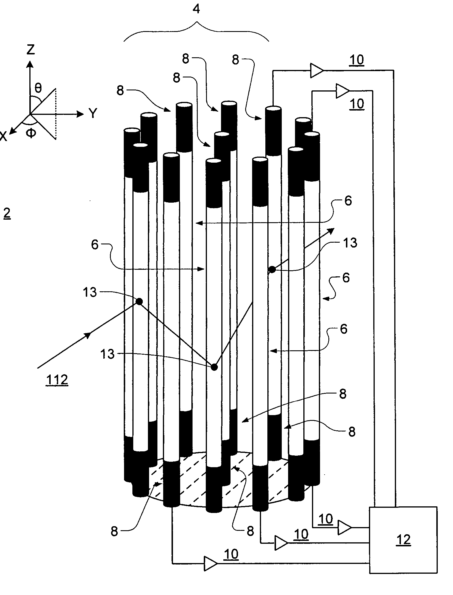
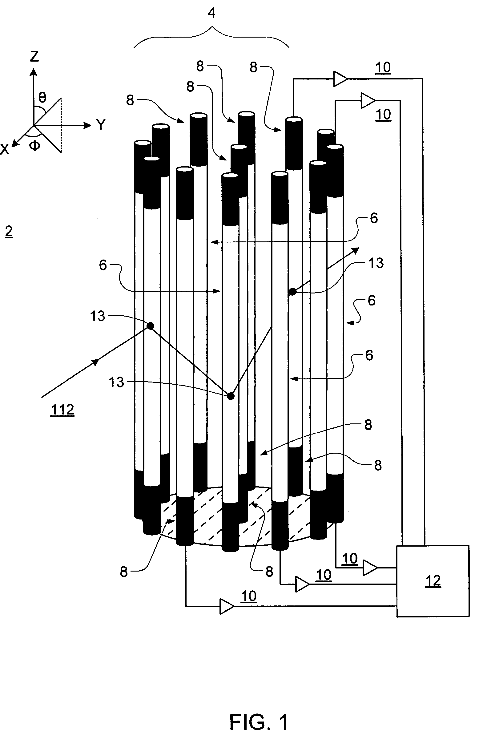
[0016] The present invention relates to a radially symmetric imaging detection system for neutrons or gamma-rays.

[0017] With respect to neutrons, the present invention measures the energy of an incident neutron, and through scattering kinematics determines the point or extended sources of the neutron. This technique is based on a known detection mechanism—fast neutron scattering off ambient hydrogen (n-p scattering). Such a detection system is configured to locate n-p scatter sites within its volume using the scintillation light generated by recoil protons, highly ionizing particles. For the neutrons that undergo at least two successive n-p scatters, an image revealing the location of a source can be constructed.

[0018]FIG. 1 shows one preferred embodiment of the imaging detection system 2 of the present invention. The design consists of a radially symmetric array 4 of multiple (in this embodiment 13) parallel scintillator bars 6. The scintillator bars 6 are preferably organic scin...


PUM


Abstract

The present invention is a radially symmetric imaging detector that measures an incident neutron's or gamma-ray's energy and identifies its source on an event-by-event basis.

Description

CROSS-REFERENCE TO RELATED APPLICATIONS [0001] The present application claims the benefit of provisional patent application Ser. No. 60 / 713,104 filed Aug. 31, 2005, which is incorporated herein by reference.GOVERNMENT SPONSORSHIP [0002] The development of the present invention was funded in part by the DoE of the United States Government under Contract No. DE-FG52-04NA25687 and by the NASA of the United States Government under Contract No. NAG5-13519.TECHNICAL FIELD [0003] The present invention relates to a system for neutron and gamma-ray detection. More specifically, it relates to a radially symmetric imaging detector that directly measures the incident radiation. BACKGROUND INFORMATION [0004] Because they are electrically neutral, neutrons and gamma-rays have been traditionally detected using indirect means. However, typical indirect techniques of the prior art, for neutrons, for example, while able to measure count rate, provide little, if any, information on the neutron's energ...

Claims


Application Information

Patent Timeline
IPC IPC(8): G01T3/06G01T1/20
CPCG01T1/20G01T3/06G01T1/2907
Inventor RYAN, JAMES M.MACRI, JOHN R.MCCONNELL, MARK L.BRAVAR, ULISSE
Owner UNIVERSITY OF NEW HAMPSHIRE
Why Eureka
Try Eureka