
Driver system and method with multi-function protection for cold-cathode fluorescent lamp and external-electrode fluorescent lamp

Active Publication Date: 2007-03-15
ON BRIGHT ELECTRONICS SHANGHAI
View PDF4 Cites 5 Cited by
  • Summary
  • Abstract
  • Description
  • Claims
  • Application Information

AI Technical Summary

Benefits of technology

[0021] Many benefits are achieved by way of the present invention over conventional techniques. For example, some embodiments of the present invention provide a driver system with one or more protection mechanisms. For example, the driver system is protected against under-voltage system power supply, over-voltage system power supply, and / or breaking of transformer secondary winding. In another example, the driver system is used to drive one or more cold-cathode fluorescent lamps and / or one or more external-electrode fluorescent lamp. Certain embodiments of the present invention provide protection against breaking of a secondary winding. The breaking of the secondary winding can cause arcing, which may damage the secondary winding. Arcing often is difficult to detect during the testing process, so it is very important to protect the driver system when the breaking of the secondary winding occurs. Some embodiments of the present invention provide protection against under-voltage system power supply. Such protection is very important because a low DC input voltage can cause current stress to a power MOSFET transistor. Certain embodiments of the present invention provide protection against over-voltage system power supply. Such protection is very important because a high DC input voltage can cause voltage stress between the drain and source of a power MOSFET transistor. Depending upon the embodiment, one or more of these benefits may be achieved. These and other benefits will be described in more detail throughout the present specification and more particularly below.

Problems solved by technology

The wire can easily be damaged by bending in the manufacturing process.
But the arcing process can produce a large amount of heat and even a visible fire.
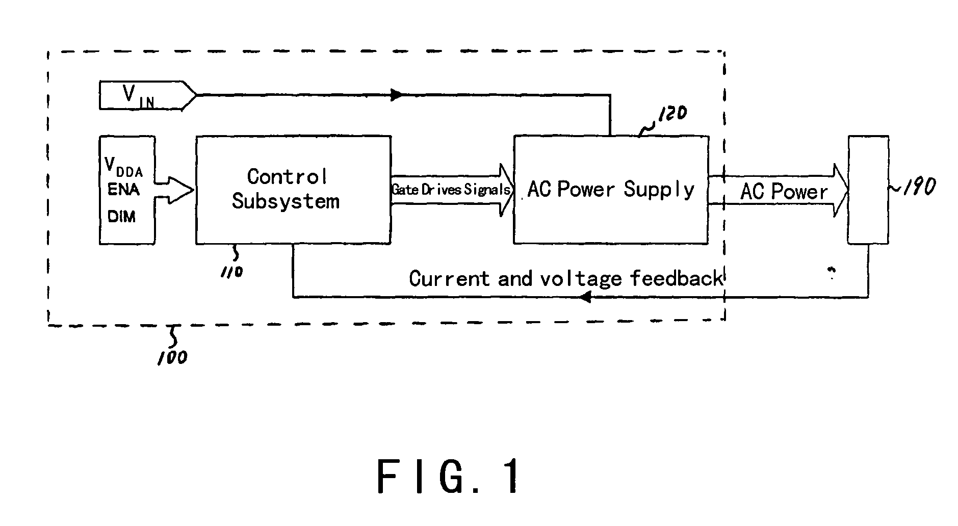
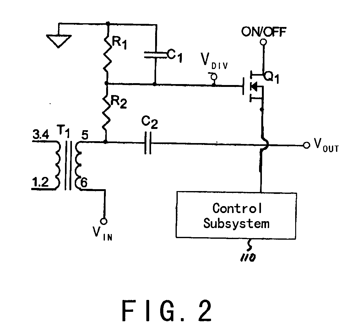
But the system as shown in FIG. 2 often cannot effectively detect breakpoints for multiple transformers.

Method used


Image

  • Driver system and method with multi-function protection for cold-cathode fluorescent lamp and external-electrode fluorescent lamp
  • Driver system and method with multi-function protection for cold-cathode fluorescent lamp and external-electrode fluorescent lamp
  • Driver system and method with multi-function protection for cold-cathode fluorescent lamp and external-electrode fluorescent lamp

Examples


Embodiment Construction

[0028] The present invention is directed to integrated circuits. More particularly, the invention provides a system and method with multi-function protection. Merely by way of example, the invention has been applied to driving one or more cold-cathode fluorescent lamps, and / or one or more external-electrode fluorescent lamps. But it would be recognized that the invention has a much broader range of applicability.

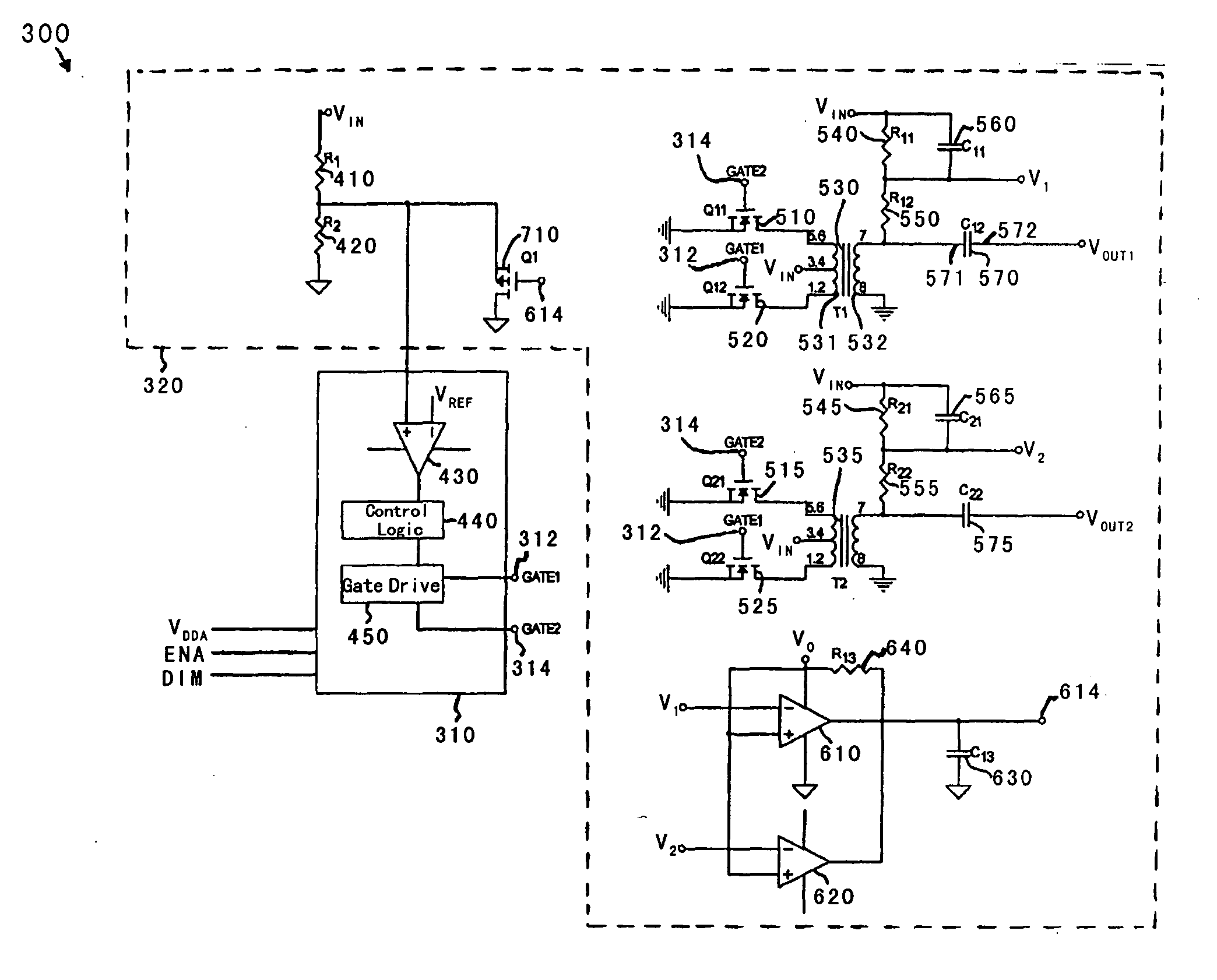
[0029]FIG. 3 is a simplified driver system according to an embodiment of the present invention. This diagram is merely an example, which should not unduly limit the scope of the claims. One of ordinary skill in the art would recognize many variations, alternatives, and modifications. The driver system 300 includes a control subsystem 310 and an AC power supply subsystem 320. The control subsystem 310 includes a comparator 430, a control logic component 440, and a gate drive component 450. The AC power supply subsystem 320 includes resistors 410, 420, 540, 545, 550, 555 and ...


PUM


Abstract

System and method for driving a cold-cathode fluorescent lamp. The system includes a control subsystem configured to generate one or more control signals, and a power supply subsystem configured to receive the one or more control signals and a DC input voltage, convert the DC input voltage to an AC output voltage, and send the AC output voltage to a cold-cathode fluorescent lamp. If the DC input voltage is lower than a predetermined threshold, the system for driving the cold-cathode fluorescent lamp is turned off in response to the one or more control signals.

Description

CROSS-REFERENCES TO RELATED APPLICATIONS [0001] This application claims priority to Chinese Patent Application No.200510102863.0, filed Sep. 13, 2005, commonly assigned, incorporated by reference herein for all purposes. STATEMENT AS TO RIGHTS TO INVENTIONS MADE UNDER FEDERALLY SPONSORED RESEARCH OR DEVELOPMENT [0002] NOT APPLICABLE REFERENCE TO A “SEQUENCE LISTING,” A TABLE, OR A COMPUTER PROGRAM LISTING APPENDIX SUBMITTED ON A COMPACT DISK. [0003] NOT APPLICABLE BACKGROUND OF THE INVENTION [0004] The present invention is directed to integrated circuits. More particularly, the invention provides a system and method with multi-function protection. Merely by way of example, the invention has been applied to driving one or more cold-cathode fluorescent lamps, and / or one or more external-electrode fluorescent lamps. But it would be recognized that the invention has a much broader range of applicability. [0005] The cold-cathode fluorescent lamp (CCFL) and external-electrode fluorescent ...

Claims


Application Information

Patent Timeline
IPC IPC(8): H05B41/36
CPCH05B41/2853H05B41/282
Inventor ZHANG, CHANGSHANYE, JUNFANG, LIEYI
Owner ON BRIGHT ELECTRONICS SHANGHAI
Learn More