Imaging apparatus

a technology of imaging apparatus and lens barrel, which is applied in the field of imaging apparatus, can solve the problems of difficult adjustment of the rotational position of the camera about the axis of the lens barrel, and achieve the effect of easy and reliable adjustmen

Inactive Publication Date: 2007-03-15
SONY CORP
View PDF1 Cites 9 Cited by
  • Summary
  • Abstract
  • Description
  • Claims
  • Application Information

AI Technical Summary

Benefits of technology

[0012] It is desirable to easily adjust the rotational position of the camera about the axis of the lens barrel.
[0015] Accordingly, the rotational position of the camera about the axis of the lens barrel can be easily and reliably adjusted by means of a simple construction.

Problems solved by technology

However, with the related art as described above, due to its inherent structure, it is difficult to adjust the rotational position of the camera about the axis of the lens barrel (about the optical axis of the photographic optical system).

Method used


Image

  • Imaging apparatus
  • Imaging apparatus
  • Imaging apparatus

Examples


first embodiment

[0036] A first embodiment of the present invention will now be described.

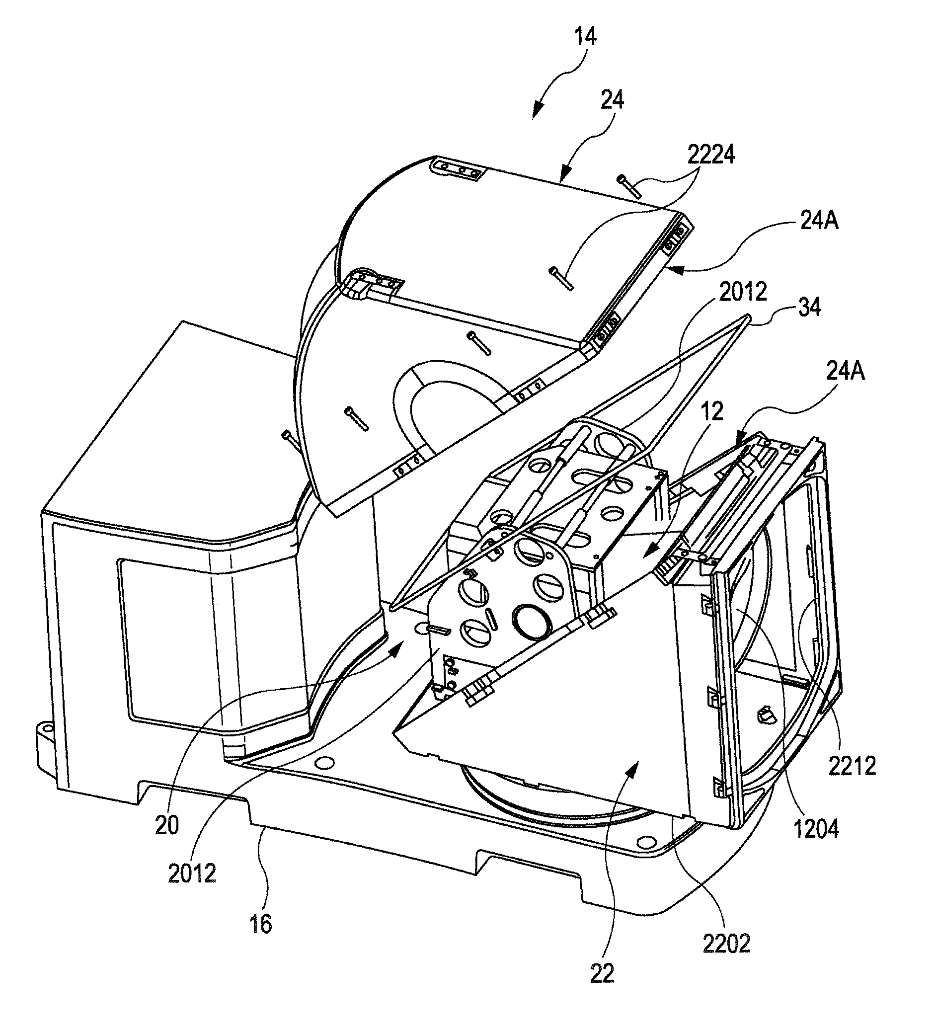
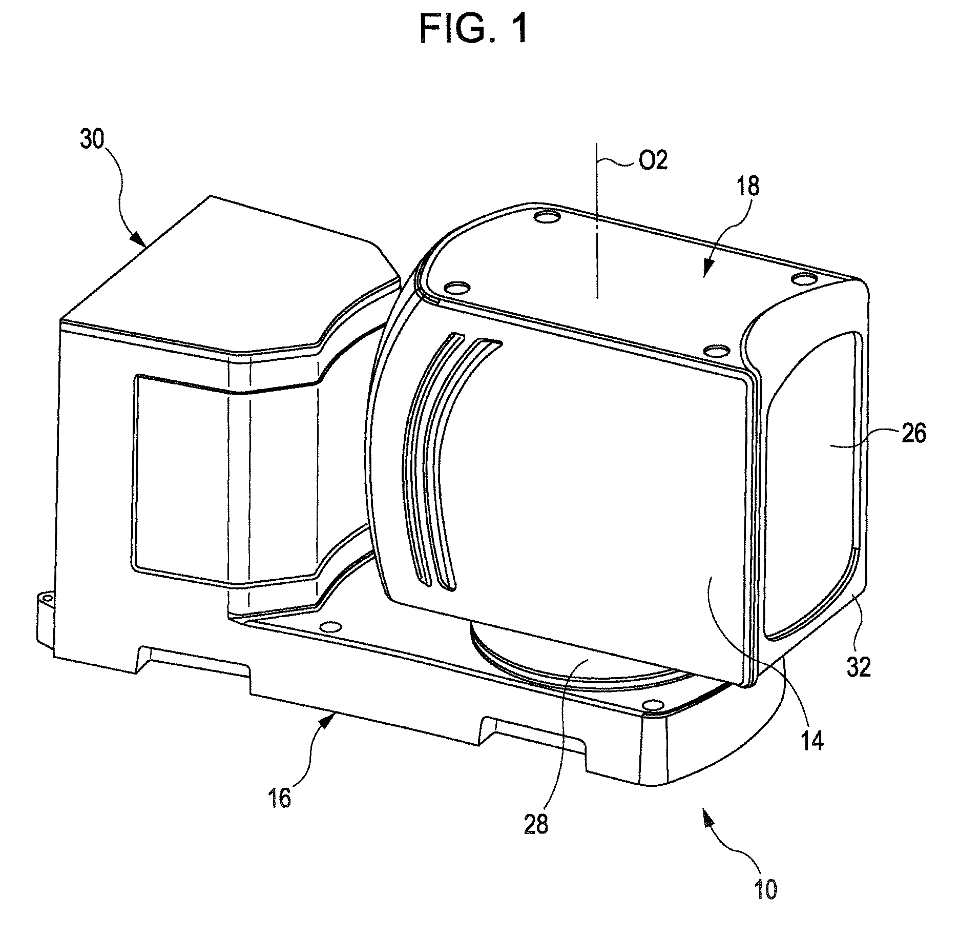
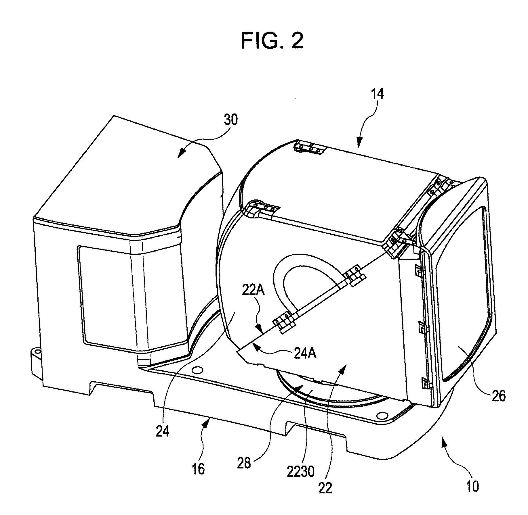
[0037]FIG. 1 is a perspective view, as seen from diagonally above, of an imaging apparatus according to this embodiment, FIG. 2 is a perspective view of an imaging apparatus 10 with a dressing cover 18 removed, FIG. 3 is a side view showing the construction of the imaging apparatus 10, and FIG. 4 is an exploded perspective view of the imaging apparatus 10.

[0038] As shown in FIGS. 2 and 3, the imaging apparatus 10 includes a base 16, a waterproof case 14 provided on the base 16, and a turning mechanism 28 for turning the waterproof case 14 about a vertical axis O2.

[0039] The waterproof case 14 is provided with a camera 12 and a rocking mechanism 20 for vertically rocking the camera 12.

[0040] In this embodiment, the dressing cover 18 is attached onto the waterproof case 14.

[0041] As shown in FIG. 2, the waterproof case 14 and the dressing cover 18 are arranged on one side of the upper surface of the base 16,...

second embodiment

[0116] Next, a second embodiment of the present invention will be described.

[0117] The second embodiment differs from the first embodiment in the configuration of the camera, the configuration of the bracket, and the mounting structure of the guide members with respect to the camera. Otherwise, the second embodiment is of the same construction as the first embodiment.

[0118]FIGS. 18 and 19 are perspective views showing the construction of the portion near a camera 50 according to the second embodiment, and FIG. 20 is a perspective view of the camera 50. In the following description of this embodiment, the same components or parts as those of the first embodiment are denoted by the same reference numerals.

[0119] As shown in FIG. 20, the camera 50 includes a case 5002, a lens barrel 5006 protruding from the front surface of the case 5002 and accommodating a photographic optical system including a photographic lens 5004, and an imaging device (not shown) such as a CCD or CMOS accommo...


PUM


Abstract

An imaging apparatus includes: a camera having a lens barrel incorporating an imaging device and a photographic optical system for introducing a subject image to the imaging device; a bracket for supporting the camera; a guide member attached onto the camera, the guide member having a cylindrical surface extending about an axis of the lens barrel in a state in which the guide member is attached on the camera; a plurality of bearing members provided to the bracket and supporting the cylindrical surface so that the cylindrical surface is rotatable about the axis of the lens barrel; and a fixing device for fixing the camera to the bracket.

Description

CROSS REFERENCES TO RELATED APPLICATIONS [0001] The present invention contains subject matter related to Japanese Patent Application JP 2005-261485 filed in the Japanese Patent Office on Sep. 9, 2005, the entire contents of which are incorporated herein by reference. BACKGROUND OF THE INVENTION [0002] 1. Field of the Invention [0003] The present invention relates to an imaging apparatus. [0004] 2. Description of the Related Art [0005] There are monitoring apparatuses that include an imaging apparatus having a camera and a bracket supporting the camera, and monitors images taken by the camera on a monitor. [0006] In monitoring apparatuses for monitoring over a large area, the camera is rocked vertically or turned around the vertical axis to obtain a plurality of image data in succession, and the plurality of image data are arranged vertically and horizontally side by side and synthesized to generate image data covering a large area. [0007] On the other hand, since the imaging region ...

Claims


Application Information

Patent Timeline
Patent Type & Authority Applications(United States)
IPC IPC(8): G02B13/16
CPCG03B15/00H04N5/2252G03B17/56G03B17/561H04N23/51G03B17/02
Inventor SAIKI, JUNICHI
Owner SONY CORP
Why Eureka
Try Eureka