Image forming apparatus, image forming method, and image forming program

Inactive Publication Date: 2007-03-15
KK TOSHIBA +1
View PDF6 Cites 33 Cited by
  • Summary
  • Abstract
  • Description
  • Claims
  • Application Information

AI Technical Summary

Benefits of technology

[0009] An object of the present invention is to provide image forming apparat

Problems solved by technology

However, K produced by overlapping each coloring material of CMY actually has no ideal K color characteristic.
The phenomenon is a factor of remarkably reducing the image quality while giving damages t

Method used


Image

  • Image forming apparatus, image forming method, and image forming program
  • Image forming apparatus, image forming method, and image forming program
  • Image forming apparatus, image forming method, and image forming program

Examples


Embodiment Construction

[0024] One embodiment of the present invention will be described below with reference to the accompanying drawings. This embodiment relates to a MFP (image forming apparatus) including an electro-photographic printer.

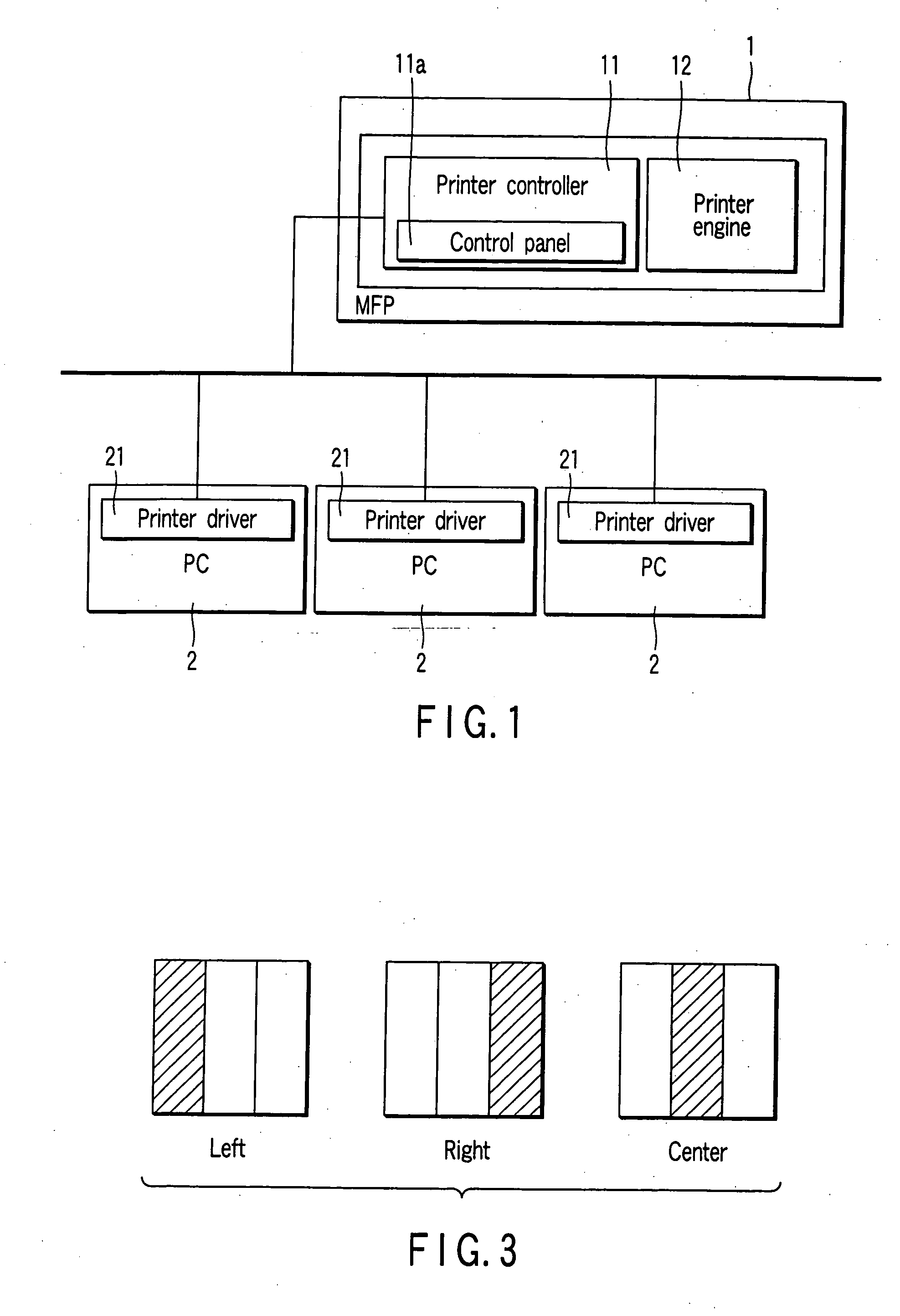
[0025]FIG. 1 is a block diagram schematically showing the configuration of a MFP and showing the environmental layout thereof.

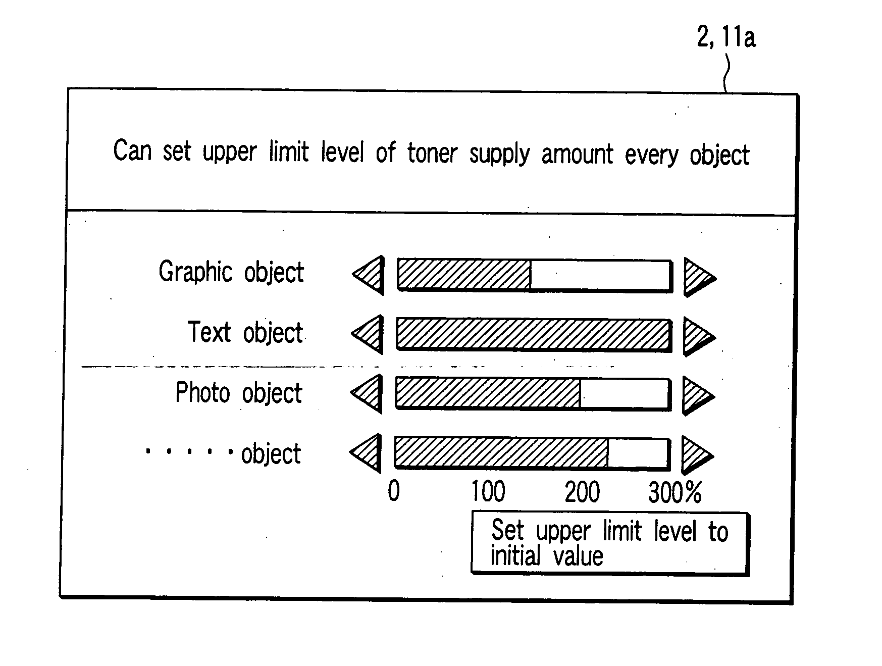
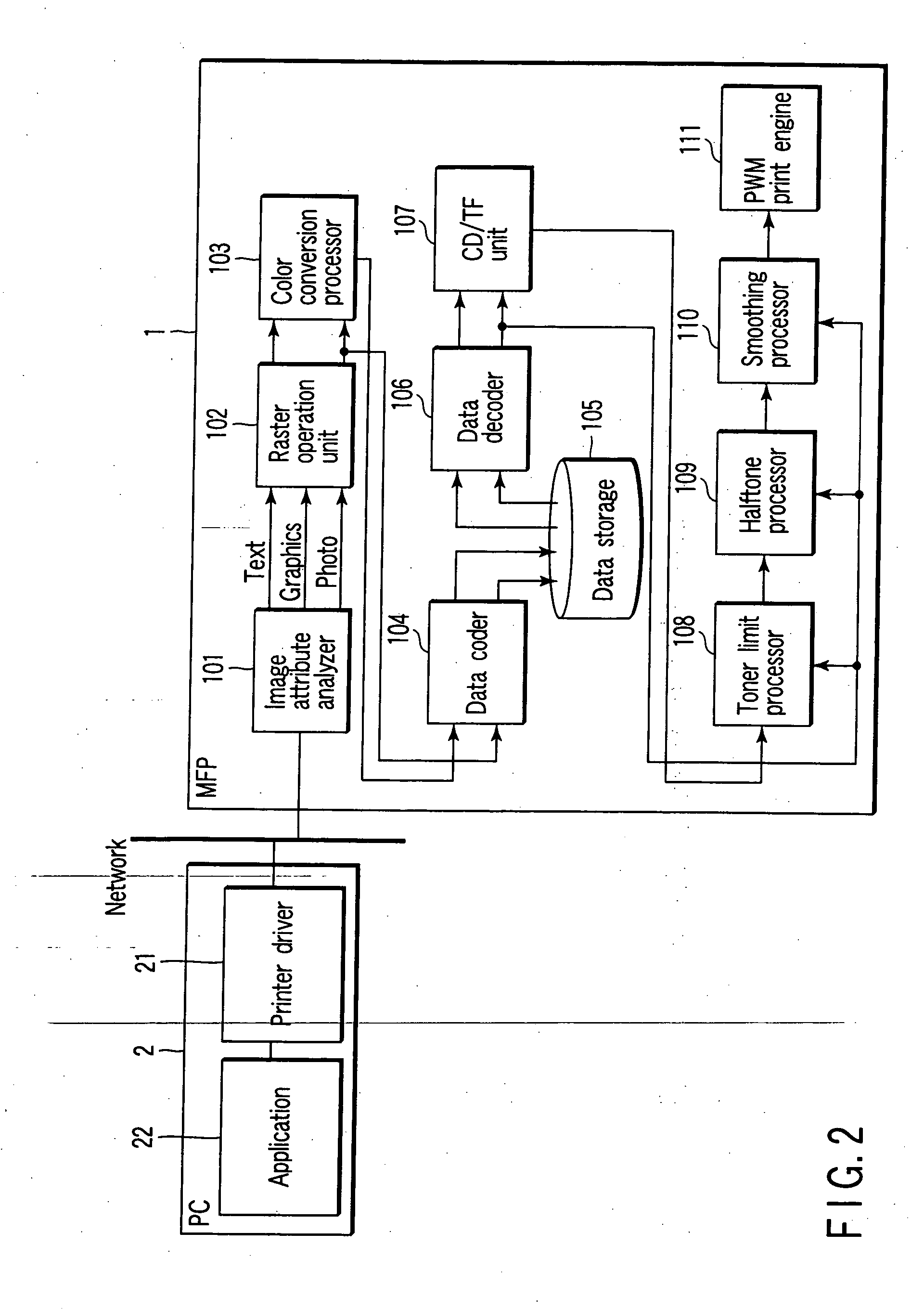
[0026] A MFP 1 includes printer controller 11 and printer engine 12. The MFP 1 further includes a control panel 11a, which accepts various setting inputs with respect to the printer controller 11. Arbitrary computer terminals 2 (printer drivers 21) connected on a network transfer PDL data showing image data structure to the MFP 1. In other words, these computer terminals 2 transfers PDL code or raster data to the printer controller 11 of the MFP 1 in accordance with interface characteristic of the MFP 1 (printer).

[0027] The MFP 1 drives and controls the printer engine 12 using the printer controller 11. The printer controller 11 expands coded ...


PUM


Abstract

According to one aspect of the present invention, there is provided an image forming apparatus comprising an analyzer analyzing an attribute of an object contained in image data, a toner limiter limiting several toners supplies corresponding to several color components based on an attribute of the object analyzed by the analyzer, and an image forming unit forming an image based on an object contained in the image data using the toner limited by the toner limiter.

Description

BACKGROUND OF THE INVENTION [0001] 1. Field of the Invention [0002] The present invention relates to various image forming apparatuses such as copier, printer and FAX. Moreover, the present invention relates to image forming method and image forming program applied to these image forming apparatuses. [0003] 2. Description of the Related Art [0004] Recently, various image forming apparatuses have come into wise use, and typically, a MFP (multi-function printer) is given. The MFP integrally handles digitized image data using various functions such as copier, printer, scanner and FAX. Moreover, the MFP temporarily stores the image data in a storage medium such as HDD, and reuses it. In the MFP given as a typical example, that is, in the image forming apparatus, the following requirements are given as a very important development item. First, it is necessary to establish architecture of simply and seamlessly handling various data. Secondary, it is necessary to reduce the apparatus cost ...

Claims


Application Information

Patent Timeline
IPC IPC(8): G06F3/12
CPCH04N1/6072H04N1/6022
Inventor NAKAHARA, NOBUHIKO
Owner KK TOSHIBA
Why Eureka
Try Eureka