Optical device and method for manufacturing the same

a technology of optical devices and manufacturing methods, applied in the direction of fluid pressure measurement, fluid pressure measurement by electric/magnetic elements, instruments, etc., can solve the problems of low manufacturing efficiency, low manufacturing efficiency, and inability to detect pressure accurately, so as to improve manufacturing efficiency and manufacturing cost of the device, the effect of detecting accuracy

Inactive Publication Date: 2007-03-15
DENSO CORP
View PDF14 Cites 8 Cited by
  • Summary
  • Abstract
  • Description
  • Claims
  • Application Information

AI Technical Summary

Benefits of technology

[0018] In the above device, the lens and the diffractive grating are formed on the substrate at a job lot. Accordingly, a detecting accuracy, a manufacturing efficiency and a manufacturing cost of the device are improved. Further, it is not necessary to position the lens and the diffractive grating.

Problems solved by technology

Therefore, a problem exists in that it is inferior in detecting accuracy of the pressure.
Further, a problem also exists in that manufacturing efficiency is low since the plural concave portions (grooves) and convex portions of the Bragg grating 55 are processed one by one by a laser such as an excimer laser, etc.
Therefore, a problem also exists in that cost is taken.

Method used


Image

  • Optical device and method for manufacturing the same
  • Optical device and method for manufacturing the same
  • Optical device and method for manufacturing the same

Examples


first embodiment

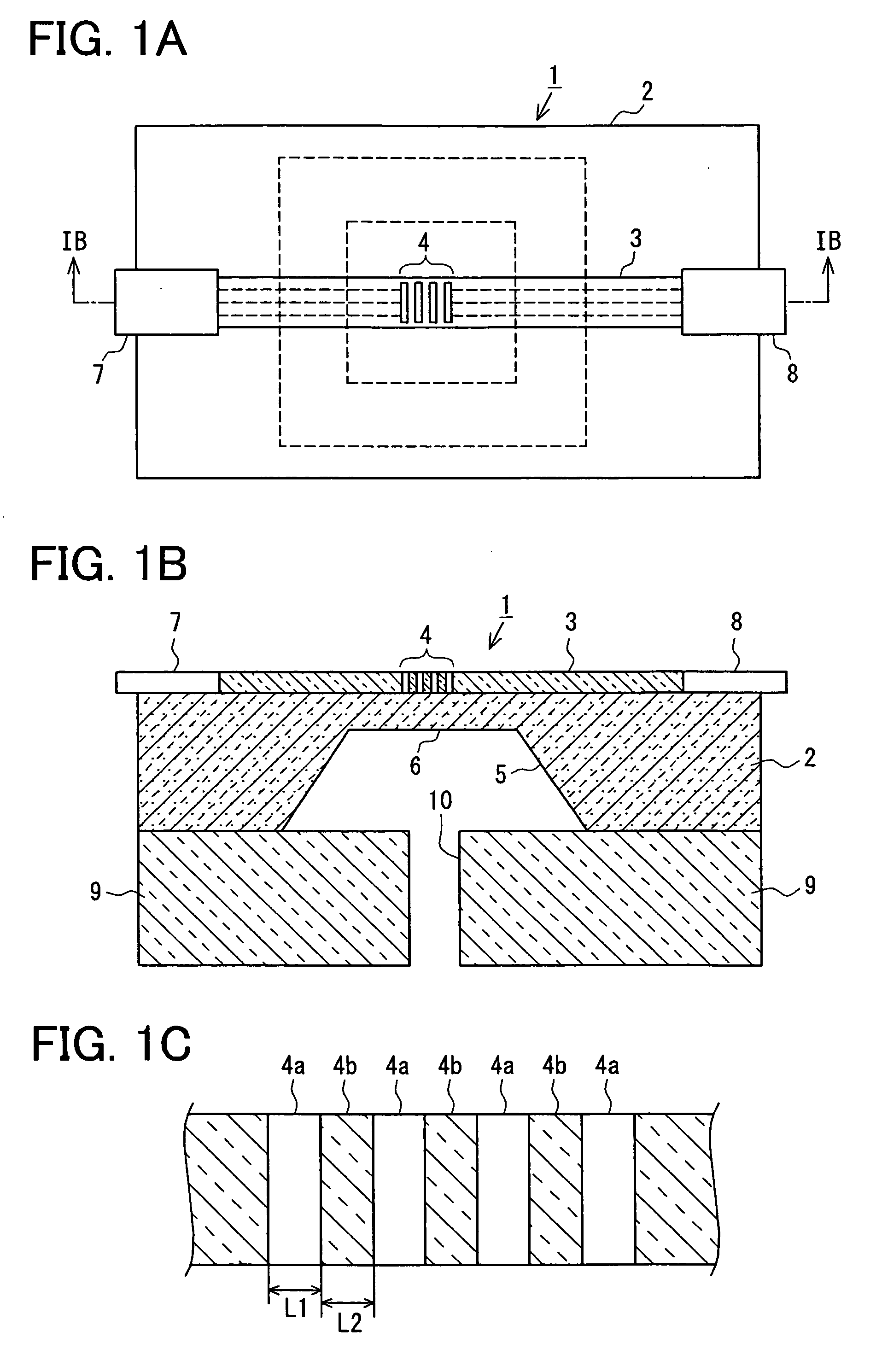
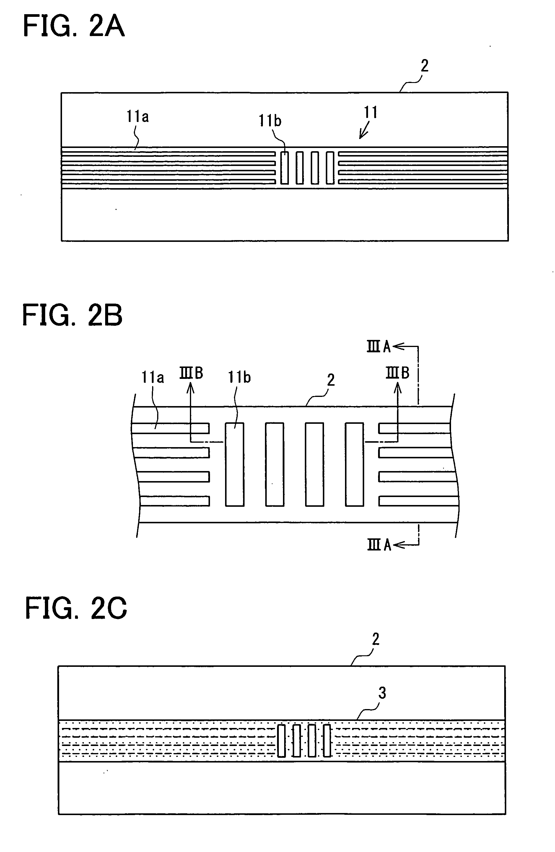
[0065] (1) As mentioned above, in accordance with the optical type pressure sensor 1 and its manufacturing method of the first embodiment mode, the optical waveguide path 3 having the Bragg grating 4 can be formed on one substrate face of the silicon substrate 2, and the diaphragm 6 can be formed on the other substrate face.

[0066] Namely, a structure for forming the Bragg grating 4 on one substrate face of the same silicon substrate 2 and forming the diaphragm 6 on the other substrate face is set instead of a structure in which the optical waveguide path is adhered to the substrate face by an adhesive layer as in the background art. Therefore, no pressure applied to the diaphragm 6 is buffered by the adhesive layer.

[0067] Accordingly, the pressure applied to the diaphragm 6 can be accurately transmitted to the Bragg grating 4. Therefore, detecting accuracy of the pressure applied to the diaphragm 6 can be raised.

[0068] (2) Further, the optical waveguide path 3 having the Bragg gra...

second embodiment

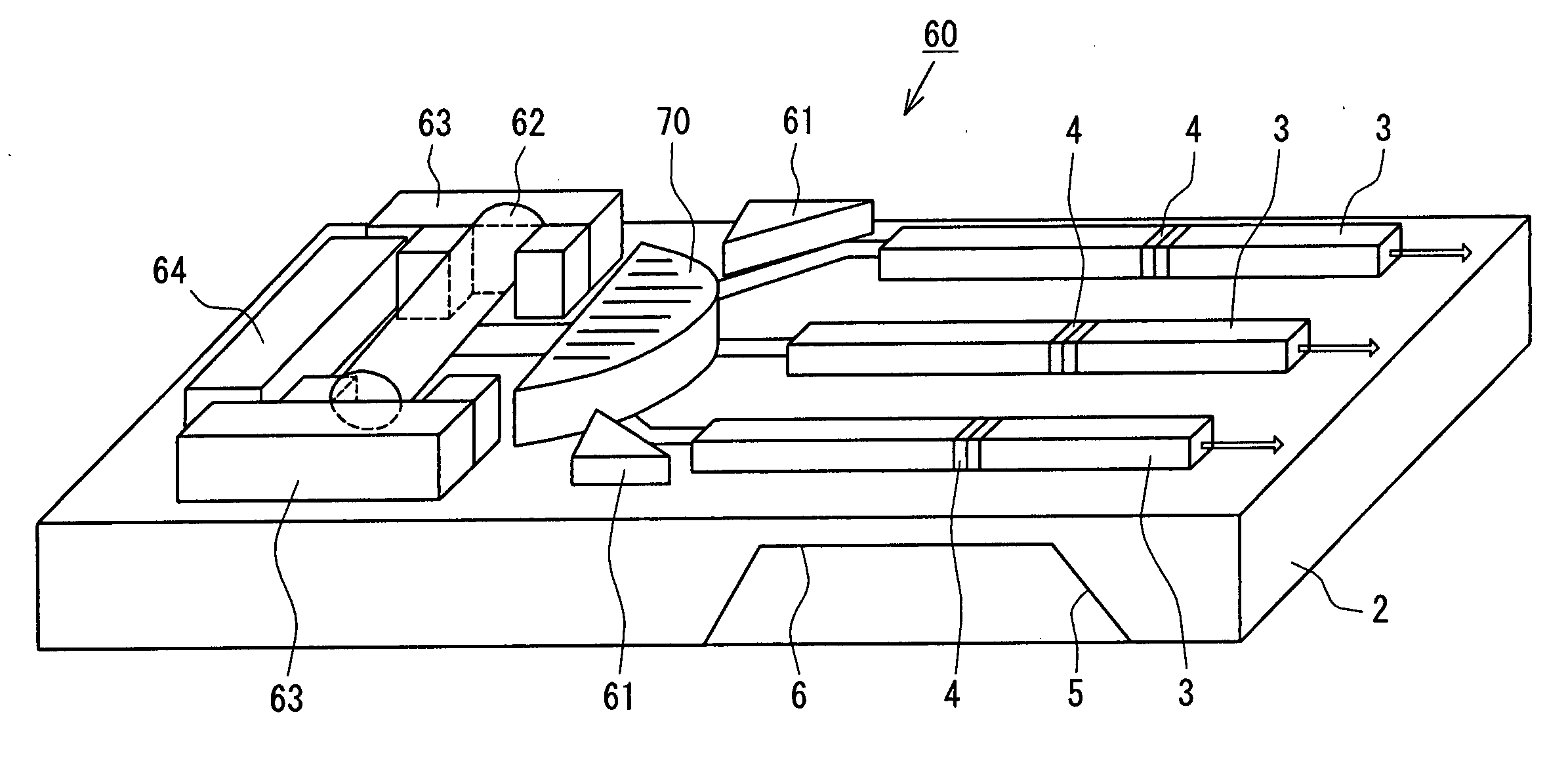
[0097] (1) As mentioned above, in accordance with the optical type pressure sensor 60 and its manufacturing method of the second embodiment mode, plural optical type pressure sensors for detecting the pressure of a fluid at plural measuring points can be collectively formed in one silicon substrate. Therefore, manufacturing efficiency can be raised in comparison with a method for individually manufacturing the plural optical type pressure sensors.

[0098] Furthermore, since each optical type pressure sensor has the same structure as the optical type pressure sensor 1 of the above first embodiment mode, the pressure at the plural measuring points can be detected with high precision.

[0099] (2) Further, the optical element 70 having both functions of a lens and a diffraction grating and the plural optical waveguide paths 3 arranged in the advancing direction of each divided light emitted from this optical element 70 can be collectively manufactured in the same silicon substrate 2 by the...


PUM


Abstract

A method for manufacturing an optical device is provided. The device includes an optical waveguide path having a Bragg grating and a movable portion disposed near the Bragg grating. A displacement of the movable portion provides a change of spacing of the Bragg grating so that a light passing through the optical waveguide path is changed. The optical device detects the physical quantity based on a change of the light. The method includes steps of: forming the optical waveguide path with the Bragg grating on a first part of a silicon substrate; and forming the movable portion on a second part of the silicon substrate.

Description

CROSS REFERENCE TO RELATED APPLICATION [0001] This application is based on Japanese Patent Application No. 2005-263637 filed on Sep. 12, 2005, the disclosure of which is incorporated herein by reference. FIELD OF THE INVENTION [0002] The present invention relates to an optical device and a method for manufacturing the same. BACKGROUND OF THE INVENTION [0003] An optical type pressure sensor for detecting e.g., pressure of a fluid in an optical type is formerly known as the optical device of this kind. FIGS. 9A to 9D are explanatory views showing this optical type pressure sensor, where FIG. 9A is a plan view, and FIG. 9B is a front view, and FIG. 9C is a partial enlarged view and FIG. 9D is a cross-sectional view seen from arrow IXD-IXD of FIG. 9C. [0004] This optical type pressure sensor 50 has an optical waveguide path 51. Optical fibers 52, 53 are connected to both ends of the optical waveguide path 51. A Bragg grating 55 is formed in an intermediate portion of an optical path of ...

Claims


Application Information

Patent Timeline
Patent Type & Authority Applications(United States)
IPC IPC(8): G02B6/26
CPCG01L9/0076
Inventor OOHARA, JUNJITAKEUCHI, YUKIHIRO
Owner DENSO CORP
Why Eureka
Try Eureka