Control system having verification module

a verification module and control system technology, applied in the field of control systems, can solve the problems of unpredictably altering the behavior of the control system, unable to reconfigure the conventional control system, and typically designed to only have limited purpose(s) and functionality

Inactive Publication Date: 2007-03-15
ROCKWELL AUTOMATION TECH
View PDF10 Cites 16 Cited by
  • Summary
  • Abstract
  • Description
  • Claims
  • Application Information

AI Technical Summary

Benefits of technology

[0013] The present inventors have recognized the desirability of reliable, failure-resistant control systems with expanded capabilities. The present inventors further have recognized that, in some embodiments, such an improved control system could be achieved by adding one or more additional modules to a conventional primary control system, where each additional modu...

Problems solved by technology

Although control systems such as the control system 2 shown in FIG. 1 are useful, such control systems are typically designed to have only limited purpose(s) and functionality.
Despite the desirability of providing such additional functions in some circumstances, it is not possible to reconfigure conventional control systems such as the control ...

Method used


Image

  • Control system having verification module
  • Control system having verification module
  • Control system having verification module

Examples


Embodiment Construction

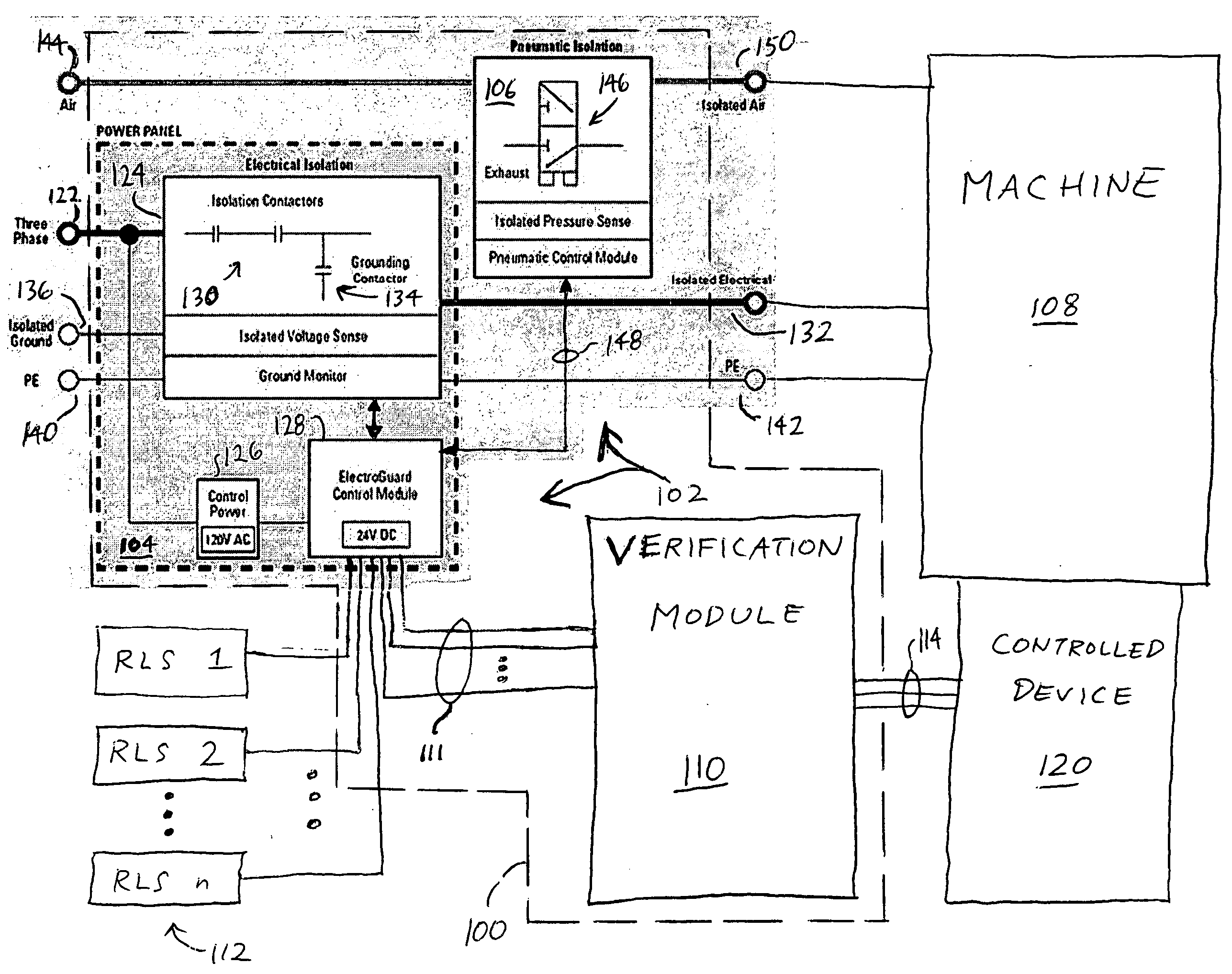
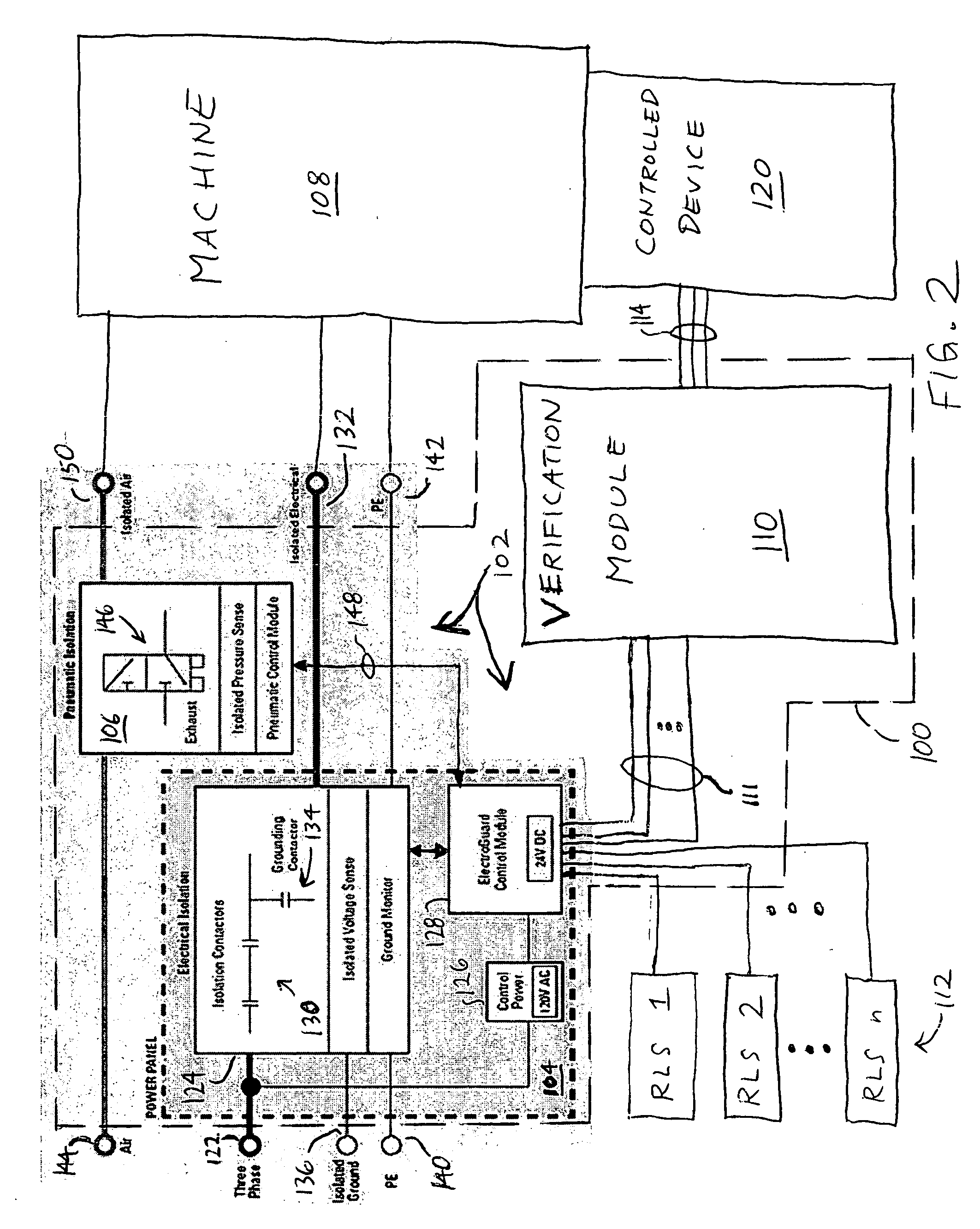
[0020] In at least some embodiments, the present invention can be part of a “safety system” used to protect human life and limb in an industrial or other environment. Nevertheless, the term “safety” as used herein is not a representation that the present invention will make an industrial or other process safe or that other systems will produce unsafe operation. Safety in an industrial or other process depends on a wide variety of factors outside of the scope of the present invention including, for example: design of the safety system, installation and maintenance of the components of the safety system, and the cooperation and training of individuals using the safety system. Although the present invention is intended to be highly reliable, all physical systems are susceptible to failure and provision must be made for such failure.

[0021] Referring to FIG. 2, an improved control system 100 in accordance with certain embodiments of the present invention is shown to be coupled to and in...


PUM


Abstract

The present invention relates to an intermediate module capable of being implemented in conjunction with a safety isolation system, as well as a control system employing such an intermediate module and related operational method. In one embodiment, the intermediate module includes a first input terminal capable of receiving a first signal from an additional device that is at least one of the safety isolation system and another device, and a first output terminal capable of providing a second signal to a controlled device. The intermediate module additionally includes at least one safety relay circuit that receives at least one of the first signal and a first intermediate signal based upon the first signal, and that generates in response at least one of the second signal and a second intermediate signal upon which the second signal is based. The safety relay circuit includes at least one redundant circuit component.

Description

CROSS-REFERENCE TO RELATED APPLICATIONS [0001] -- STATEMENT REGARDING FEDERALLY SPONSORED RESEARCH OR DEVELOPMENT [0002] -- FIELD OF THE INVENTION [0003] The present invention relates to control systems such as, for example, industrial control systems for disconnecting, grounding and / or isolating industrial loads with respect to various sources of power. BACKGROUND OF THE INVENTION [0004] In a variety of environments, including for example industrial environments, there is a need for control systems that are capable of governing the operation of one or more pieces of equipment or machinery in a manner that is highly reliable. Such control systems often employ a high degree of redundancy in their various circuits and other components, so as to guarantee or nearly guarantee that the control systems will achieve intended goals in operating the controlled equipment / machinery and, in the event of failures, that the control systems will operate in such manners that the control systems and...

Claims


Application Information

Patent Timeline
IPC IPC(8): G05B11/01
CPCG05B9/03G05B9/02
Inventor SCHARNICK, MICHAEL R.ZBYTOWSKI, STEPHEN A.
Owner ROCKWELL AUTOMATION TECH
Why Eureka
Try Eureka