Device for distributing flat articles using a transport system

Inactive Publication Date: 2007-03-22
KOENIG & BAUER AG
View PDF14 Cites 16 Cited by
  • Summary
  • Abstract
  • Description
  • Claims
  • Application Information

AI Technical Summary

Benefits of technology

[0009] The advantages which can be achieved by the present invention lie, in particular, in that the device operates without the use of rapidly and discontinuously moved parts, such as, for example, are required by the above-described signature shunt. Furthermore, no large spacing distances are required to be formed between objects which are following each other on the conveying track in order to be able to transport those objects, without problems, to different delivery positions.
[0012] It is sufficient for the device for distributing flat objects, in accordance with the present invention, if each paddle wheel has only a single paddle and thus has only a single object receiving compartment. It is also possible, in accordance with the present invention, to provide two paddles in each paddle wheel. This simplifies the balancing of the paddle wheels and, in comparison with the embodiment provided with a single paddle, makes no noticeable increase of the circumference of the paddle wheel necessary.
[0016] A vertical section of the conveying track is preferably arranged following the transverse cutting device, which vertical section can be used to space the individual printed products, which are delivered to the conveying track by the transverse cutting device, apart from each other on the conveying track. The paddle wheels are preferably serially or sequentially arranged along a horizontal section of the conveying track in order to make the delivery of the individual flat objects or products into the compartments of the paddle wheels simpler.

Problems solved by technology

The objects, which are conveyed on the conveying track, tend to push into a compartment of the paddle wheel because of their inherent weight, if such a compartment is available.

Method used


Image

  • Device for distributing flat articles using a transport system
  • Device for distributing flat articles using a transport system

Examples


Embodiment Construction

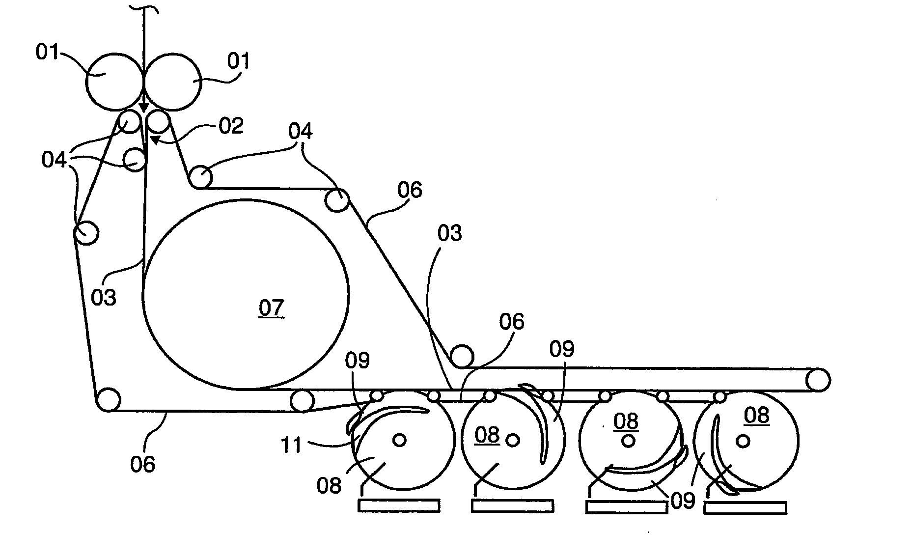
[0022] An inlet of the device for transporting flats objects in accordance with the present invention, as represented in FIG. 1, is constituted by a transverse cutting device 01, such as, for example, a cutting cylinder pair 01. As illustrated by an arrow, a strand of imprinted webs of material, such as, for example, paper webs, is fed from above out of a superstructure, which is not specifically represented, to the cutting cylinder pair 01. One cylinder of the cutting cylinder pair 01 has a cutter which, in cooperation with a countersupport of the other cylinder of the cutting cylinder pair 01, cuts a section, having the size of a page, off from the strand during every revolution of the cutting cylinder pair 01. The object which is obtained in this manner, and in particular which object is a printed product, enters an inlet nip 02 of a conveying track 03. Conveying track 03 is constituted by endless belts 06, such as, for example, by transport belts 06, which are circulating over a...


PUM


Abstract

Flat objects are distributed by a device which includes a transport section that is used to transport a stream of flat objects to be distributed, and a plurality of sequentially arranged paddle wheels or delivery fans, each of which has at least one component that is configured to receive an object from the transport section. Each paddle wheel delivers its object to a distribution point. The paddle wheels can be rotated, with respect to each other, to provide a phase shift which permits each of a number of objects, which corresponds to the number of paddle wheels in the sequence, to be received by a compartment of a different one of the number of paddle wheels.

Description

CROSS-REFERENCE TO RELATED APPLICATIONS [0001] This application is the U.S. national phase, under 35 U.S.C. 371, of PCT / EP2004 / 052525, filed Oct. 13, 2004; published as WO2005 / 035409 A1 on Apr. 21, 2005 and claiming priority to DE 103 47 572.9, filed Oct. 14, 2003, the disclosures of which are expressly incorporated herein by reference.FIELD OF THE INVENTION [0002] The present invention is directed to a device and to a method for delivering flat objects by the use of a conveying track. The flat objects are deposited in a plurality of paddle wheels or delivery fans that have object receiving compartments which are out of phase with each other. BACKGROUND OF THE INVENTION [0003] A delivery device is typically employed, in particular, at an outlet of a rotary printing press, to deliver individual signatures, formed from a continuous web of imprinted paper webs, to a plurality of conveyor belts. A generally known delivery device of this type is described, for example, in DE 101 16 346 A...

Claims


Application Information

Patent Timeline
Patent Type & Authority Applications(United States)
IPC IPC(8): B41F13/54B65H29/12B65H29/40B65H29/58
CPCB65H29/12B65H2701/1932B65H29/58B65H29/40B65H2404/632
Inventor RATZ, HOLGER
Owner KOENIG & BAUER AG
Why Eureka
Try Eureka