Method of mounting a LED module to a heat sink

a technology of led modules and heat sinks, which is applied in the direction of semiconductor devices for light sources, light and heating apparatus, planar light sources, etc., can solve the problems of reducing reliability by using adhesives, and achieve the effect of ensuring reliability and remaining cost efficien

Active Publication Date: 2011-05-12
KONINKLIJKE PHILIPS ELECTRONICS NV
View PDF15 Cites 12 Cited by
  • Summary
  • Abstract
  • Description
  • Claims
  • Application Information

AI Technical Summary

Benefits of technology

[0005]It is an object of the present invention to at least partly overcome these problems, and to provide an improved method for mounting an LED module to a heat sink. In particular, it is an object to provide a method for mounting of an LED module to a heat sink that enables an enhanced reliability over time while remaining cost efficient.

Problems solved by technology

However, an arrangement where the LED module is screwed to the heat sink requires additional manufacturing steps as the heat sink and the LED housing must be provided with threads.
Further, the use of adhesives typically reduces the reliability over time for the device as the temperature generated by the LED package affects the adhesive.

Method used


Image

  • Method of mounting a LED module to a heat sink
  • Method of mounting a LED module to a heat sink
  • Method of mounting a LED module to a heat sink

Examples


Embodiment Construction

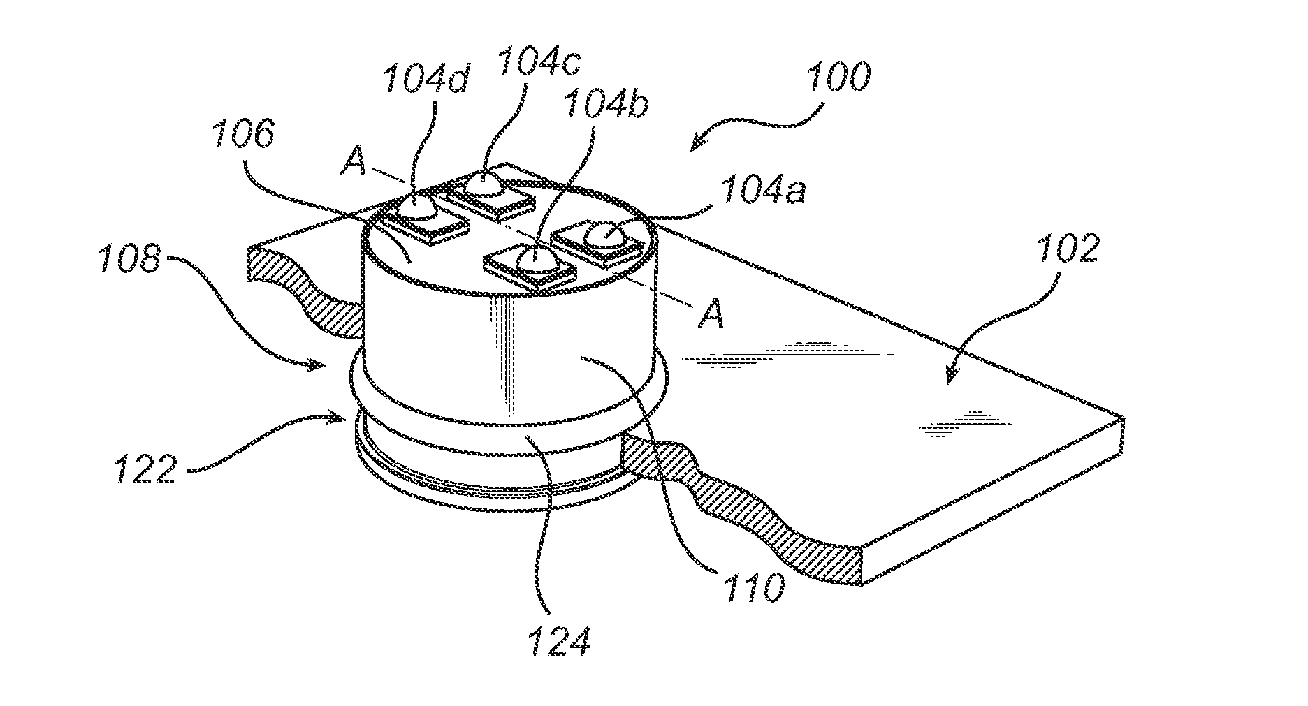
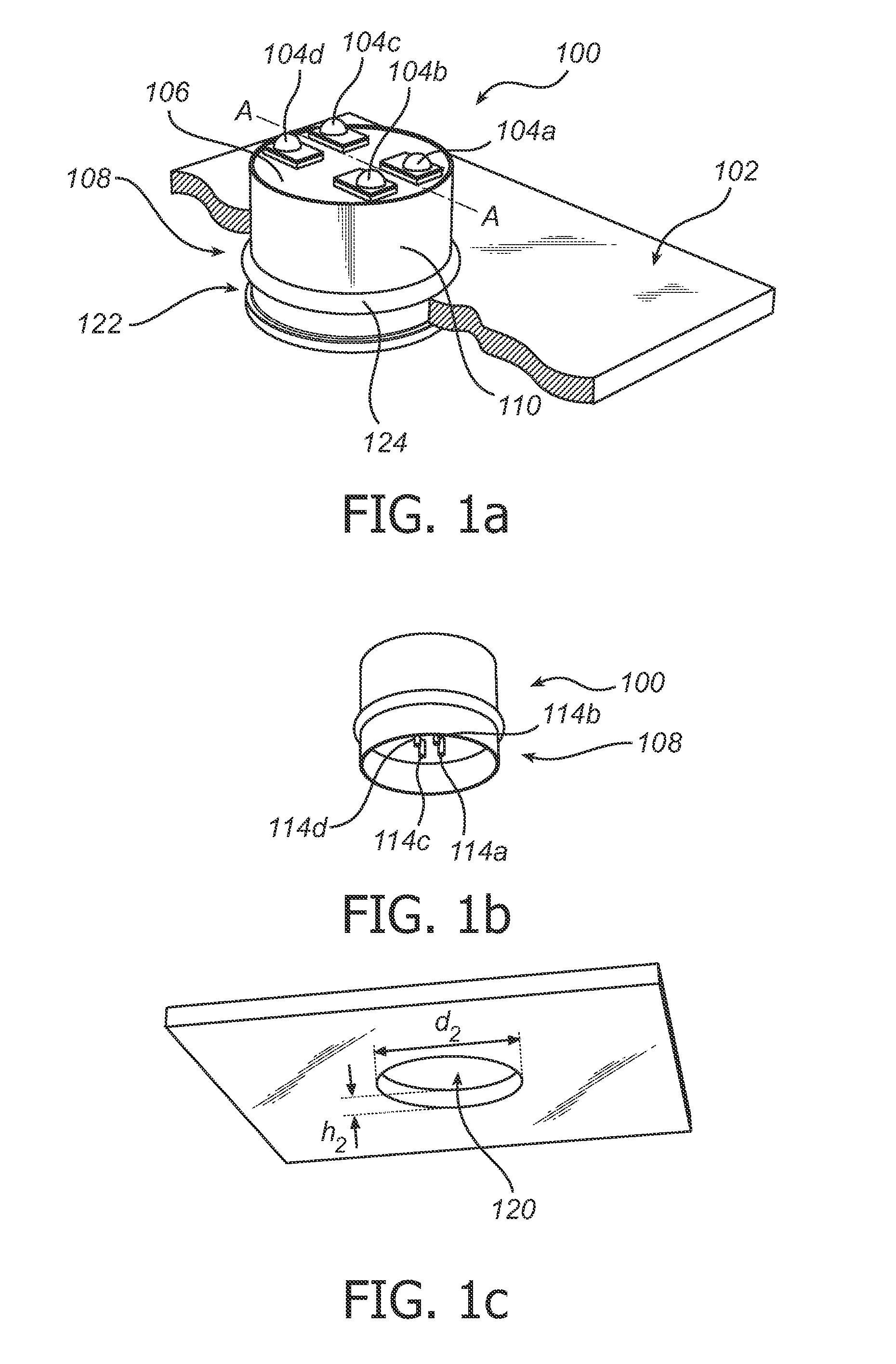
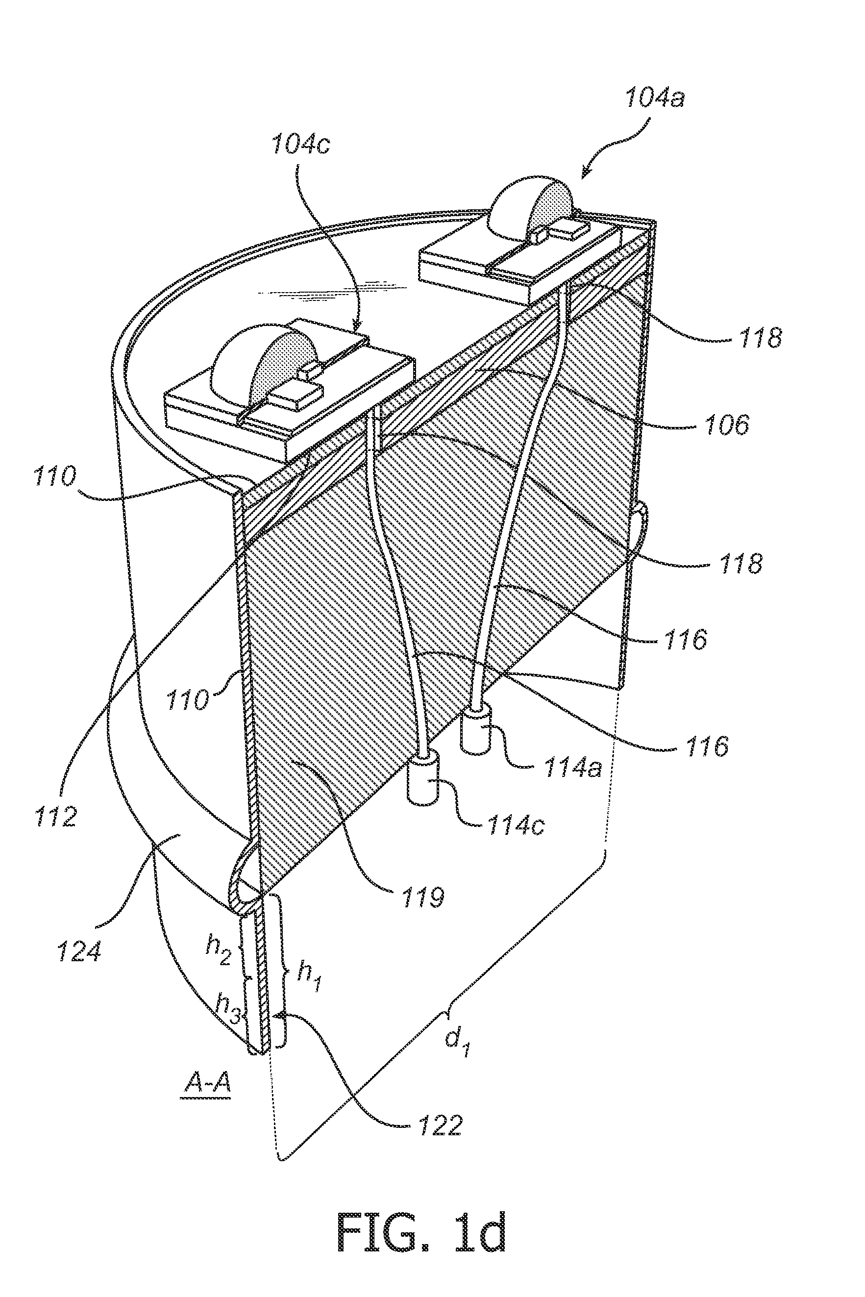
[0023]Referring now to the drawings and to FIG. 1a-b in particular, there is depicted an LED module 100 having a cylinder shaped body 108. The LED module is arranged on a heat sink 102, which may be part of a lamp housing comprising a socket (not shown) to which the LED module 100 may be connected. The LED module 100 comprises four LED packages 104a-d mounted on a printed circuit board (PCB) 106 arranged at the top of the cylinder shaped body 108. The LED packages may be standard packages, such as, for example, LUXEON® REBEL from Philips. The cylinder shaped body 108 is covered with a thermally conductive casing 110 made of a material having a high thermal conductivity, such as metal, e.g. aluminum. The thickness of the casing range from 0.5-1.5 mm depending on the material in the casing. By arranging an electrically insulating thermal pad 112 of a material having high thermal conductivity between each LED package 104a-d and the PCB 106, and connecting the bottom of the PCB metalliz...


PUM


Abstract

A method of mounting a light emitting diode (LED) module (100) to a heat sink (102), the method comprising the steps of placing the LED module (100) in a hole (120) in the heat sink (102); and expanding a portion of the LED module (100) such that the LED module (100) is secured to the heat sink (102). The method provides a cost efficient way of securing an LED module to a heat sink where the mount has a high reliability over time.

Description

FIELD OF THE INVENTION[0001]The present invention relates to a method of mounting an LED module to a heat sink.BACKGROUND OF THE INVENTION[0002]To facilitate mounting of LED packages, it has been proposed to arrange the LED package in an LED module which can be screwed and / or glued to the heat sink.[0003]WO 2007 / 075143A1 discloses a high power LED housing consisting of one or more LEDs to form an LED assembly fitted into a metal body having an upper portion and a lower portion. The lower portions of the LED housing has threads on its exterior surface for screwing the LED housing into a socket shaped in a heat sink.[0004]However, an arrangement where the LED module is screwed to the heat sink requires additional manufacturing steps as the heat sink and the LED housing must be provided with threads. Further, the use of adhesives typically reduces the reliability over time for the device as the temperature generated by the LED package affects the adhesive. Thus, there is a need for an ...

Claims


Application Information

Patent Timeline
Patent Type & Authority Applications(United States)
IPC IPC(8): H01L33/64
CPCF21K9/00F21S2/005F21V19/004F21V29/004F21V29/74F21Y2105/001F21V29/20F21V29/507F21Y2101/02F21V29/70F21K9/20F21Y2105/10F21Y2115/10F21V17/16F21V19/00F21V29/00
Inventor BRUNNER, JOS GEORGE ANTONYOEPTS, WOUTER
Owner KONINKLIJKE PHILIPS ELECTRONICS NV
Why Eureka
Try Eureka