

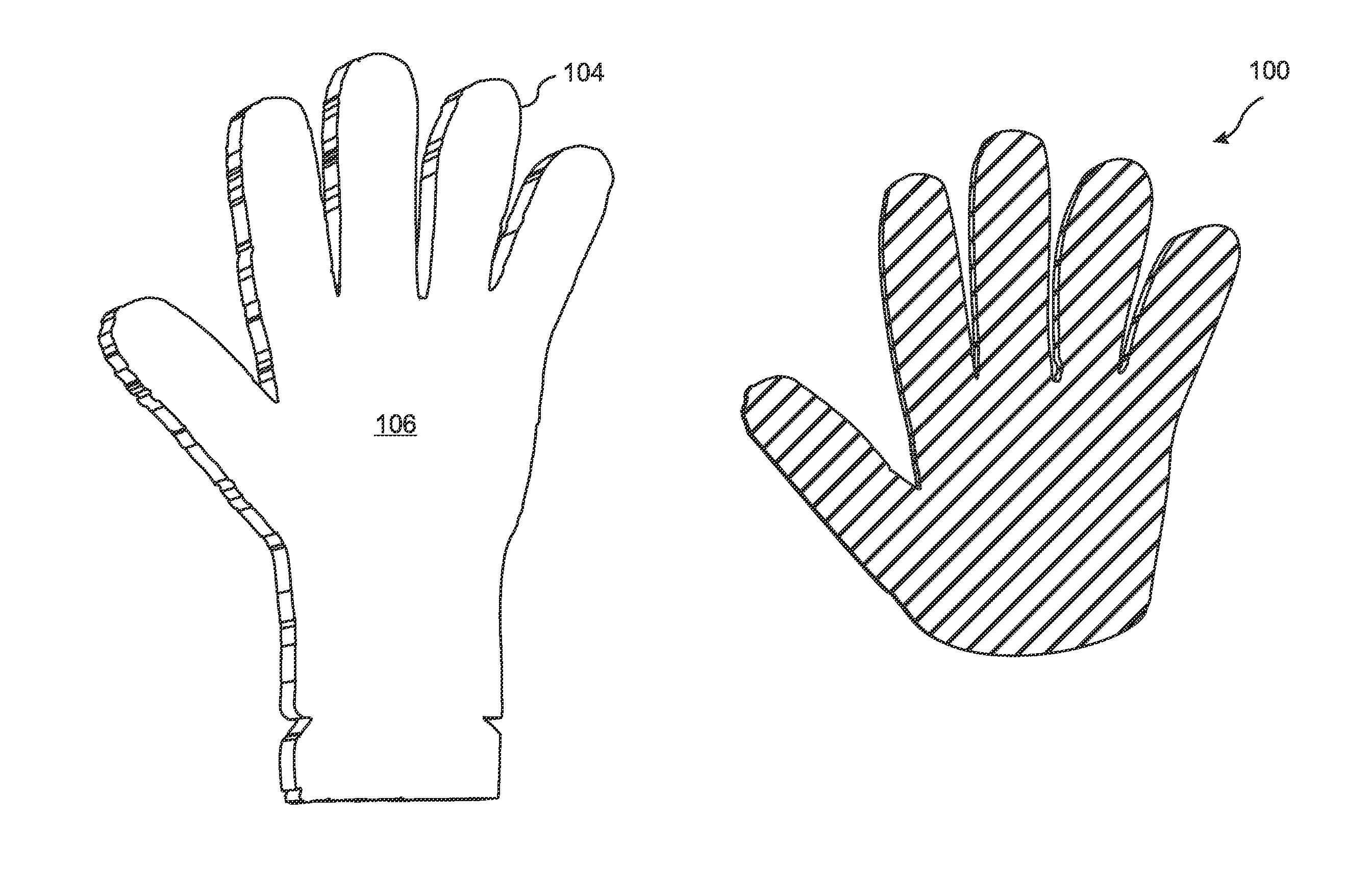
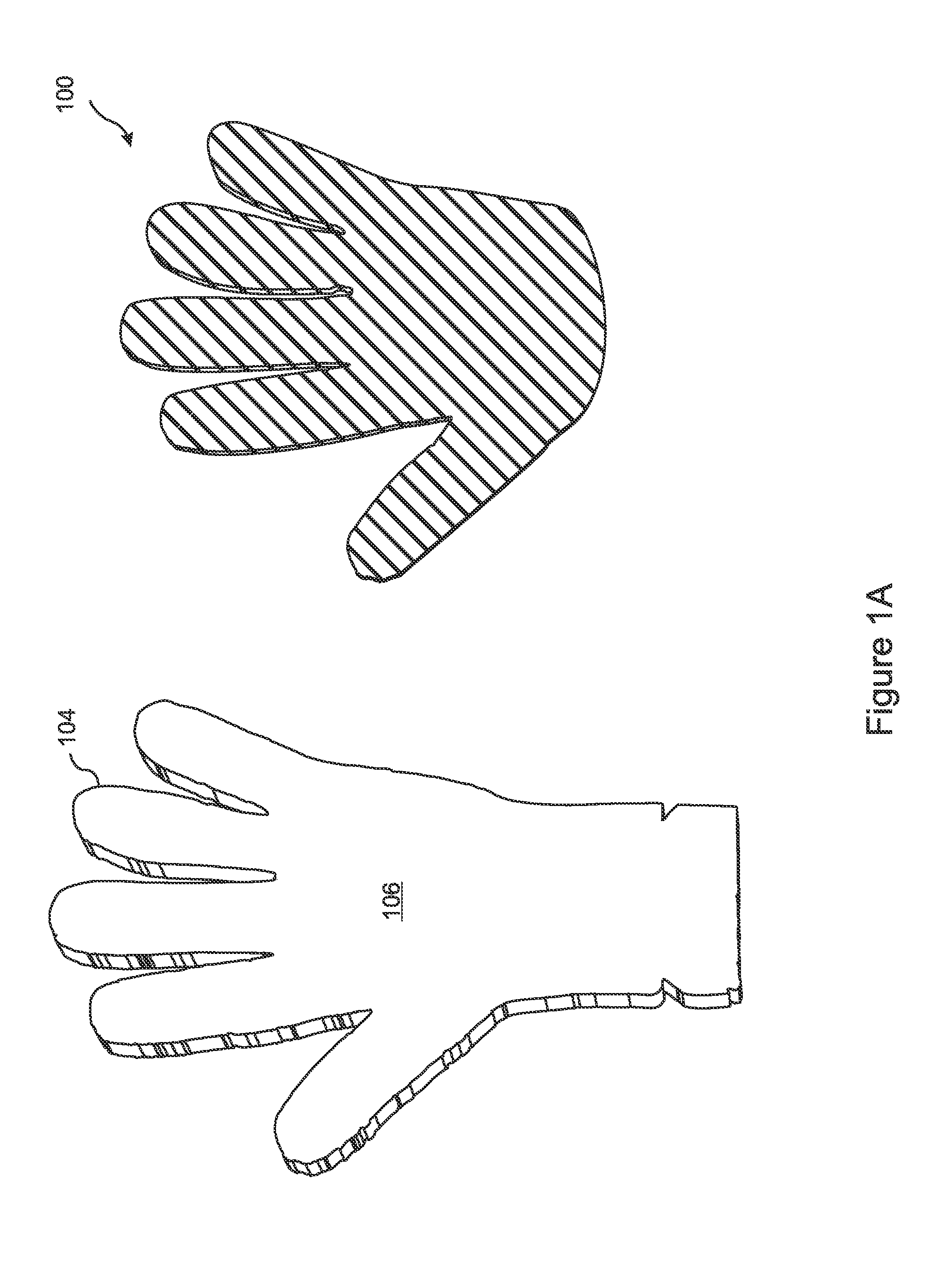
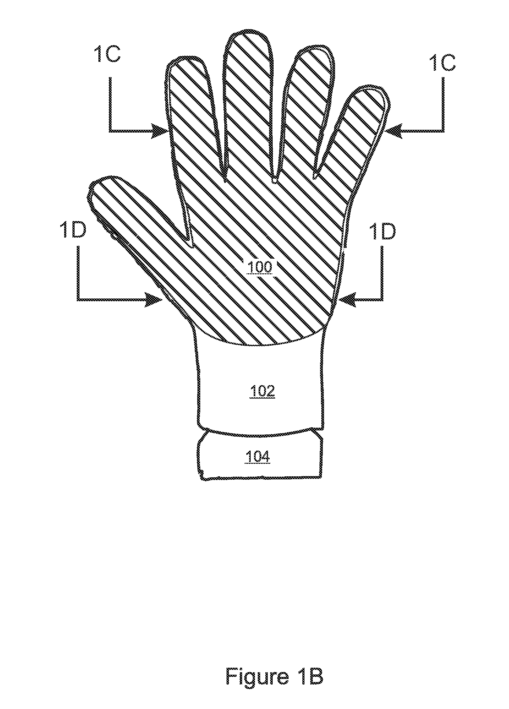
Three dimensional glove with performance-enhancing layer laminated thereto
a technology of three-dimensional gloves and performance enhancement layers, which is applied in the field of protective gloves, can solve the problems of inability to meet the needs of specialized equipment and methods, inability to meet the needs of glove manufacturing, etc., and achieve the effect of increasing the circumference of the glove shell fingers
- Summary
- Abstract
- Description
- Claims
- Application Information
AI Technical Summary
Benefits of technology
Problems solved by technology
Method used
Image

Examples
example 1
Knit Shell with Insert and Laminate Preform Including Grip And Graphics Layers
[0097]Glove shell: 210 denier nylon 13 gauge knit shell[0098]Insert: 220 denier of construction 100×60 epi of PET fiber woven or 30 denier Nylon at 100×100 epi bonded inside the shell[0099]Laminate preform:[0100]Grip layer: polyether thermoplastic urethane (“TPU”) of hardness 80 shore of 25 microns thickness[0101]CYK graphics layer: fusible inks of 5-12 microns thickness[0102]Adhesive Layer: polyether thermoplastic urethane adhesive layer, 25 micron thick, that bonds the graphics layer and grip layer to the glove shell at 350 degrees Fahrenheit[0103]Manufacturing Process: The adhesive layer is printed with the graphics layer, then the grip layer is laminated on top of the other two layers to complete the 3-ply laminate preform material. The 210 denier knit shell is mounted on the 3D laminating form. The laminate preform material is cut to shape and laminated to the glove shell on the 3D laminating form in ...
example 2
Knit Shell with TPU / Grain-Elastomer / 30 Denier Nylon Woven / PSA Laminate Preform
[0104]Glove shell: 210 denier nylon 13 gauge knit shell[0105]Insert: 220 denier 100×60 epi of PET fiber woven or 30 denier nylon at 100×100 epi bonded inside the glove shell[0106]Laminate preform:[0107]Grip layer: Polyether thermoplastic urethane of hardness 85 shore of 25 microns thickness[0108]CYK graphics layer: fusible inks of 5-12 microns thickness[0109]Adhesive tie layer: Polyether thermoplastic urethane adhesive between 12 and 25 microns thick[0110]Mechanical layer: 30 denier woven nylon 100×100 epi[0111]Filler layer: SB rubber in solvent with 220+600 grit silicone carbide filler added in a 4.5:1 ratio to the elastomer by weight[0112]Adhesive: Rosinated SBR blend in a solvent-based pressure sensitive adhesive (PSA)[0113]Manufacturing process: The grip layer is printed with the graphics layer. Then the grip layer is laminated to the textile layer. The textile layer has TPU on the face side and the gr...
example 3
Knit Shell with Non-Thermoplastic PU / Grain-Elastomer-PSA Laminate Preform
[0114]Glove shell: 210 denier nylon 13 gage knit shell[0115]Insert: 220 denier of construction 100×60 epi of PET fiber woven or 140 denier 80×70 para-aramid woven or 30d Nylon at 100×100 epi bonded inside the shell[0116]Laminate preform:[0117]Grip layer: Cast non-thermoplastic polyester urethane of hardness 95 shore of 25 microns thickness[0118]CYK graphics layer: fusible inks of 5-12 microns thickness[0119]Filler layer: SB rubber in solvent with 220+600 grit silicone carbide filler added at a 4.5:1 ratio to the elastomer by weight[0120]Adhesive: Rosinated SBR blend in solvent-based pressure sensitive adhesive (PSA)[0121]Manufacturing process: The grip layer is cast from a reactive mixture of polyol and isocyanate, cured, and then printed with the graphics layer. Then the grain layer and PSA layers are roll-coated to the glove shell side of the laminate preform. This completes the 4-ply laminate preform materia...
PUM
| Property | Measurement | Unit |
|---|---|---|
| surface energy | aaaaa | aaaaa |
| thickness | aaaaa | aaaaa |
| thickness | aaaaa | aaaaa |
Abstract
Description
Claims
Application Information