Optical wheel evaluation

Active Publication Date: 2007-03-22
INT ELECTRONICS MACHINES
View PDF19 Cites 59 Cited by
  • Summary
  • Abstract
  • Description
  • Claims
  • Application Information

AI Technical Summary

Benefits of technology

[0007] The invention provides a solution for optically evaluating a wheel along at least one circumference of the wheel. Image data is obtained while the wheel moves along a path having a length of at least one circumference of the wheel. The path and / or wheel can be illuminated to enhance the resulting image data. One or more attributes of the wheel are measured based on the image data. The attributes can then be used to detect one or more defects in the wheel. In one embodiment, the wheel is a rail wheel, and a rail segment is illuminated. The rail can be specially configured to enhance a contrast between the rail and the rail wheel and / or to provide a consistent path for the rail wheel to travel.

Problems solved by technology

However, to date, these solutions do not provide an effective solution for measuring other wheel attributes, such as a profile of the tread surface, that may be used to determine other defects that may impact the operable status of the wheel.
For example, a wheel may not be desirable for continued operation if it: includes a flat spot; is sufficiently out-of-round (e.g., elliptical shape); includes one or more gouges, cracks, and / or shelled areas; and / or the like.

Method used


Image

  • Optical wheel evaluation
  • Optical wheel evaluation
  • Optical wheel evaluation

Examples


Embodiment Construction

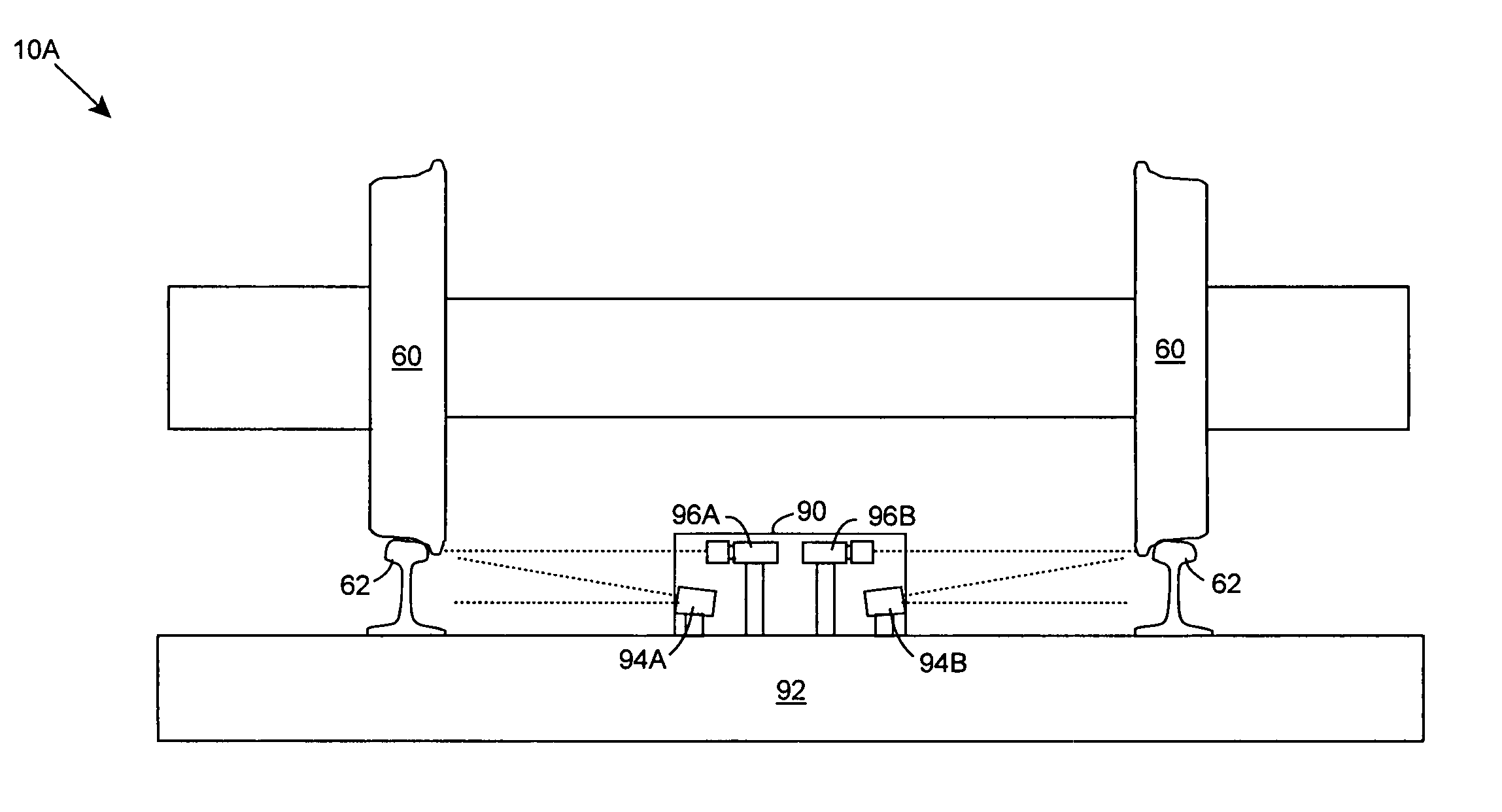
[0038] As indicated above, the invention provides a solution for optically evaluating a wheel along at least one circumference of the wheel. Image data is obtained while the wheel moves along a path having a length of at least one circumference of the wheel. The path and / or wheel can be illuminated to enhance the resulting image data. One or more attributes of the wheel are measured based on the image data. The attributes can then be used to detect one or more defects in the wheel. In one embodiment, the wheel is a rail wheel, and a rail segment is illuminated. The rail can be specially configured to enhance a contrast between the rail and the rail wheel and / or to provide a consistent path for the rail wheel to travel.

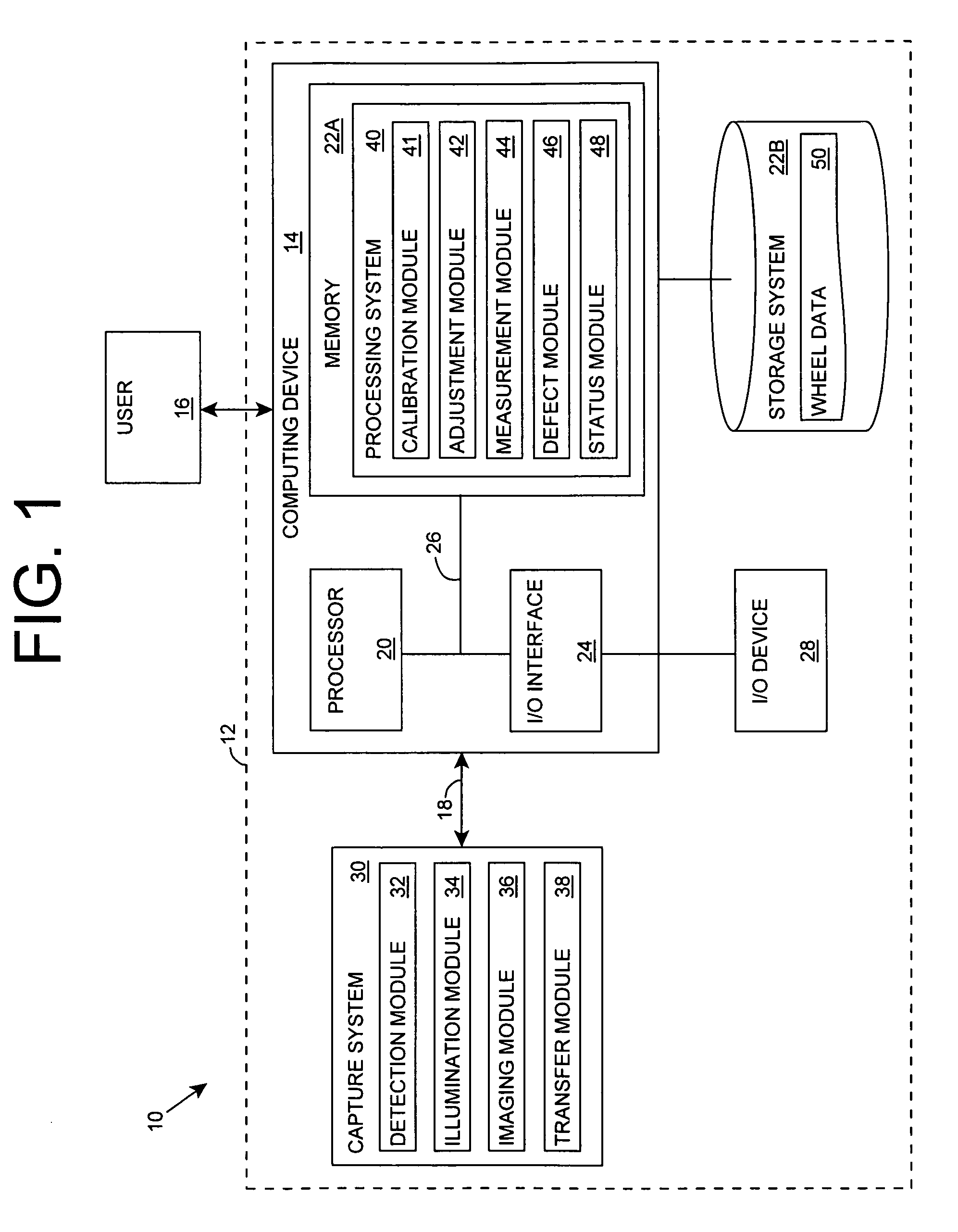
[0039] Turning to the drawings, FIG. 1 shows a schematic view of an illustrative environment 10 for evaluating a wheel according to an embodiment of the invention. To this extent, environment 10 includes a computer infrastructure 12 that can perform the various proces...


PUM


Abstract

A solution for optically evaluating a wheel along at least one circumference of the wheel is provided. Image data is obtained while the wheel moves along a path having a length of at least one circumference of the wheel. The path and / or wheel can be illuminated to enhance the resulting image data. One or more attributes of the wheel are measured based on the image data. The attributes can then be used to detect one or more defects in the wheel. In one embodiment, the wheel is a rail wheel, and a rail segment is illuminated. The rail can be specially configured to enhance a contrast between the rail and the rail wheel and / or to provide a consistent path for the rail wheel to travel.

Description

REFERENCE TO RELATED APPLICATION [0001] The current application claims the benefit of co-pending U.S. Provisional Application No. 60 / 717,263, filed on Sep. 16, 2005, which is hereby incorporated herein by reference.BACKGROUND OF THE INVENTION [0002] 1. TECHNICAL FIELD [0003] The invention relates generally to the evaluation of a wheel, and more specifically, to a solution for optically measuring the wheel. [0004] 2. BACKGROUND ART [0005] Current wheel measurement solutions, such as those described in U.S. Pat. No. 5,636,026 entitled “Method and System for Contactless Measurement of Railroad Wheel Characteristics” and U.S. Pat. No. 6,768,551 entitled “Contactless Wheel Measurement System and Method”, both of which are hereby incorporated herein by reference, effectively measure various attributes of a wheel. For example, when measuring a rail wheel, attributes such as the rim thickness, the flange thickness, the flange height, the reference groove diameter (when available), the wheel...

Claims


Application Information

Patent Timeline
IPC IPC(8): G01B11/24
CPCG01B11/25B61K9/12
Inventor MIAN, ZAHID F.MULLANEY, JEREMY C.MACALLISTER, ROBERTSCHNEIDER, THOMAS J.
Owner INT ELECTRONICS MACHINES
Why Eureka
Try Eureka