Circuit and method for soft start from a residual voltage

a residual voltage and circuit technology, applied in the direction of electric variable regulation, process and machine control, instruments, etc., can solve the problems of disadvantageous soft start performance, circuit can only be applied to buck pwm converters, etc., and achieve the effect of saving power

Active Publication Date: 2007-03-22
RICHTEK TECH
View PDF5 Cites 38 Cited by
  • Summary
  • Abstract
  • Description
  • Claims
  • Application Information

AI Technical Summary

Benefits of technology

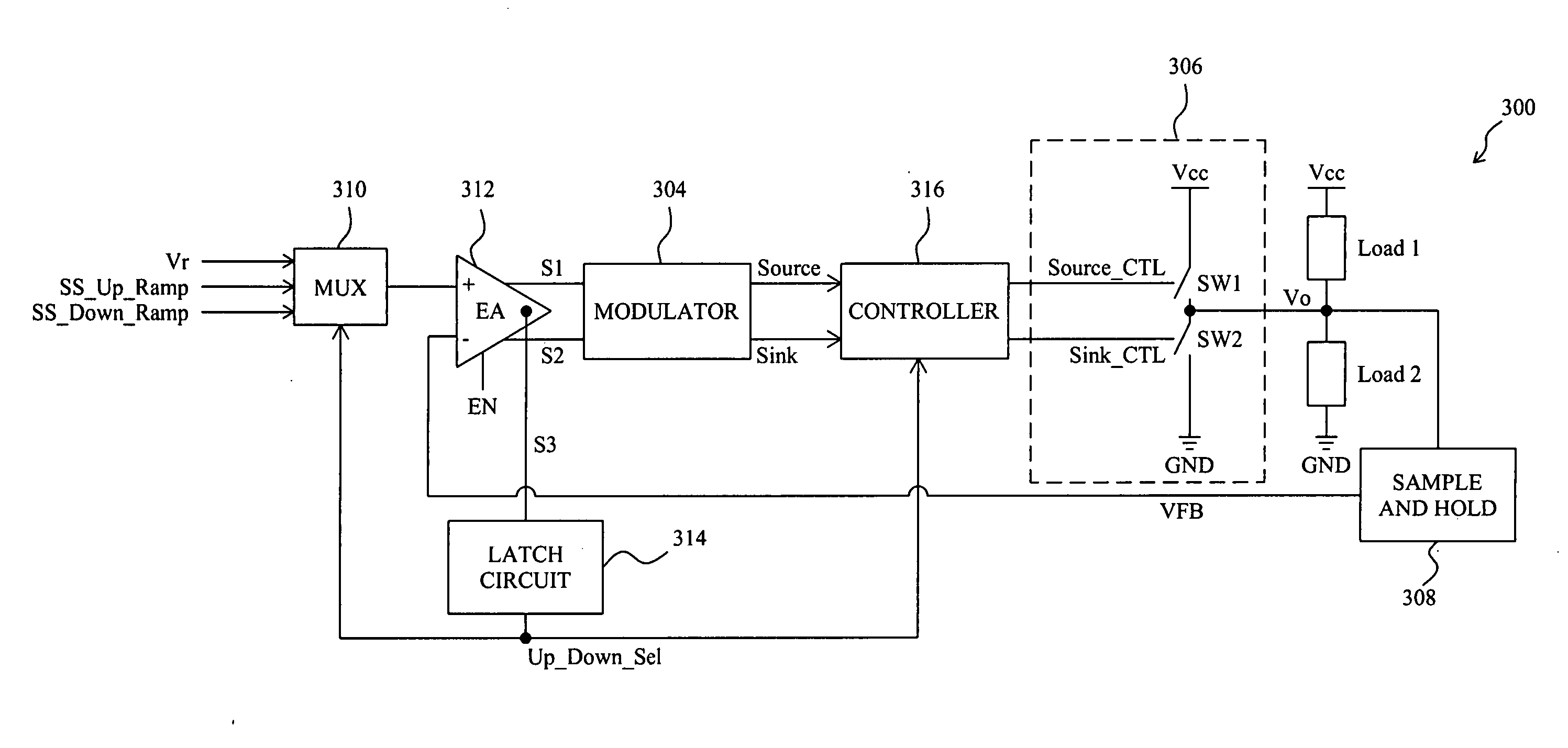
[0006] An object of the present invention is to provide a circuit and method for a system to soft start from a residual voltage, thereby saving power and requiring no extra component.

Problems solved by technology

However, such circuit can be only applied to buck PWM converter.
However, this art needs an extra capacitor, and the ramp signal for the output voltage to first compare is an RC discharge curve, which is disadvantageous to the soft start performance.

Method used


Image

  • Circuit and method for soft start from a residual voltage
  • Circuit and method for soft start from a residual voltage
  • Circuit and method for soft start from a residual voltage

Examples


Embodiment Construction

[0016] To illustrate a soft start method according to the present invention, FIG. 3 provides a waveform diagram of various signals when an output has a residual voltage during a soft start period, in which waveform 200 represents the voltage Vo on the output, waveform 202 represents a feedback signal VFB proportional to the voltage Vo, waveform 204 represents a ramp signal SS_Up_Ramp to compare with the feedback signal VFB, waveform 206 represents an original enable signal EN, and waveform 208 represents an applied enable signal EN1 for the system really to start up. As shown by the waveform 206, upon the original enable signal EN transiting to high level, a soft start begins, and the ramp signal SS_Up_Ramp begins to rise up. By the method according to the present invention, the ramp signal SS_Up_Ramp is compared with the feedback signal VFB. If the output has a residual voltage such that the initial level of the feedback signal VFB is higher than the ramp signal SS_Up_Ramp, as show...


PUM


Abstract

A circuit and method for soft start of a system compare a feedback signal produced from an output voltage of the system with a ramp signal to generate a comparison signal, and enables the system once the comparison signal indicating the ramp signal reaches the feedback signal, such that the output voltage becomes active from a residual voltage toward a target level.

Description

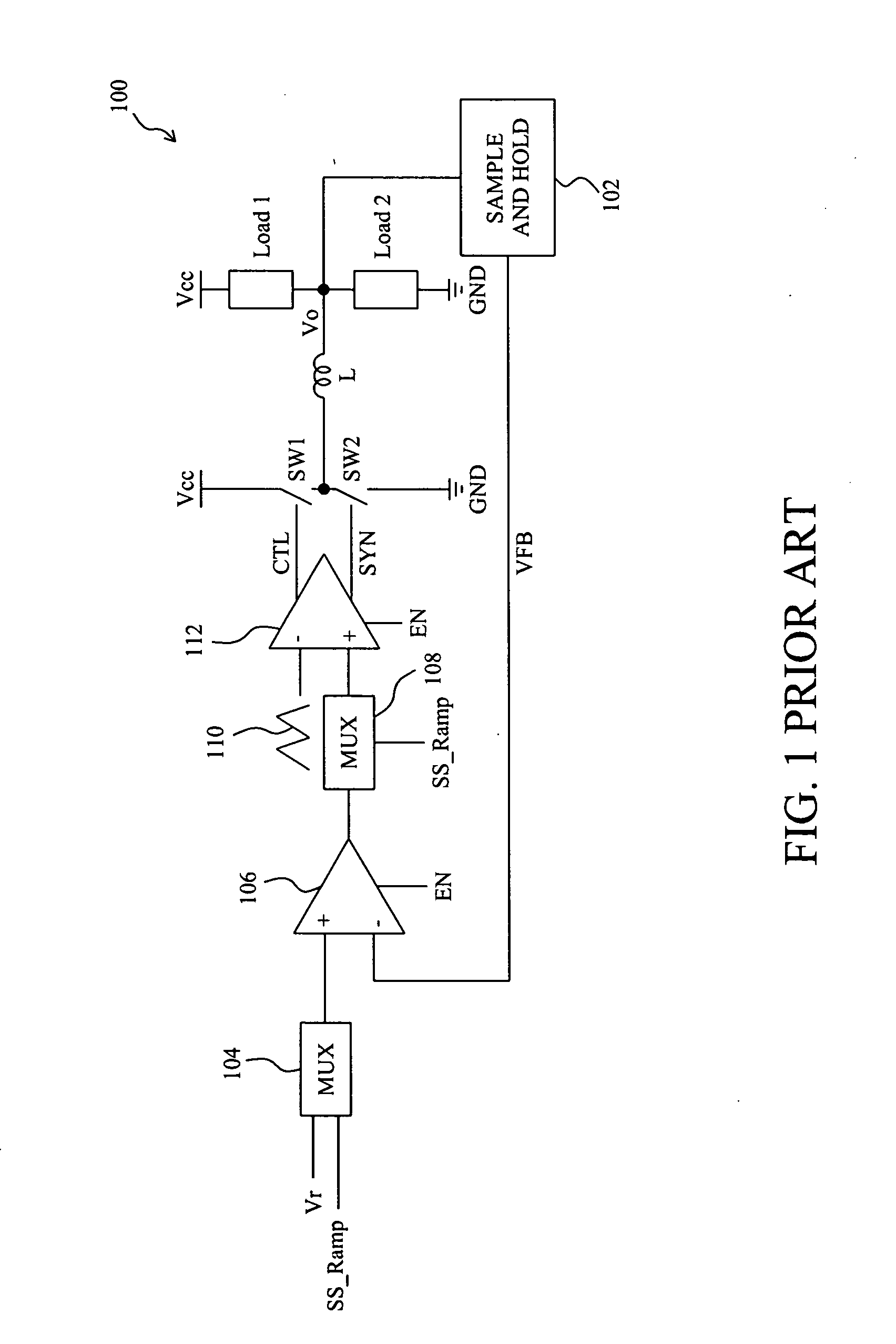
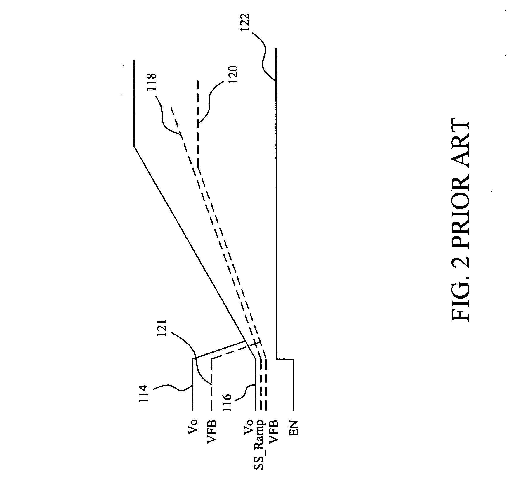
FIELD OF THE INVENTION [0001] The present invention is related generally to a soft start circuit and method and, more particularly, to a circuit and method for soft start from a residual voltage. BACKGROUND OF THE INVENTION [0002] Many systems employ soft start function for the systems to smoothly start up when system power on to reduce the impact during the start up and to prevent overloading to some components and overvoltage in the systems. FIG. 1 is a simplified diagram of a conventional pulse width modulation (PWM) buck converter 100 with soft start function, in which two switches SW1 and SW2 connected in series between supply voltage Vcc and ground GND are switched by signals CTL and SYN, respectively, to convert the input voltage Vcc to an output voltage Vo for loads Load1 and Load2, sample, and hold unit 102 produces feedback signal VFB from the output voltage Vo, error amplifier 106 has an inverting input connected with the feedback signal VFB and a non-inverting input conn...

Claims


Application Information

Patent Timeline
Patent Type & Authority Applications(United States)
IPC IPC(8): H02M1/00
CPCH02M2001/0025H02M1/36Y10S323/901H02M3/156H02M1/0025
Inventor CHEN, ISAAC Y.CHEN, AN-TUNGTAI, LIANG-PIN
Owner RICHTEK TECH
Why Eureka
Try Eureka