Steerable interbody fusion cage

a fusion cage and interbody technology, applied in the field of intervertebral cages, can solve the problems of increasing the morbidity of anterior in-situ cage placement, large dissection, plif and tlif approaches, and weakening existing posterior elements, and achieves the effect of minimal invasiveness and bone-sparing

Active Publication Date: 2007-03-22
CTL MEDICAL CORP
View PDF19 Cites 311 Cited by
  • Summary
  • Abstract
  • Description
  • Claims
  • Application Information

AI Technical Summary

Benefits of technology

[0017] The preferred embodiment provides a streamlined, slender straight contour with a central hinge or other articulating apparatus that allows the introduction of the cage into the operative field and disc space in a minimally invasive, bone-sparing manner. After partial insertion, the hinge component is activated, allowing the operator to steer the cage anterior-medially within the disc space to an anterior-central position within the intervertebral space. In this state the cage is shaped like a crescent, chevron or boomerang.

Problems solved by technology

This can lead to pinching and irritation on the nerves, causing pain.
There are several drawbacks with existing approaches and techniques, such that further research and improved designs are desirable.
Increased morbidity of anterior in-situ cage placement is not justified when less anatomic correction of the disc space is possible.
Additionally, current PLIF and transverse lumbar interbody fusions (TLIF) cage and allograft placements require large dissections for exposure.
PLIF and TLIF approaches also weaken existing posterior elements via bony destruction resulting from the operative procedure used to access the disc space.

Method used


Image

  • Steerable interbody fusion cage
  • Steerable interbody fusion cage
  • Steerable interbody fusion cage

Examples


Embodiment Construction

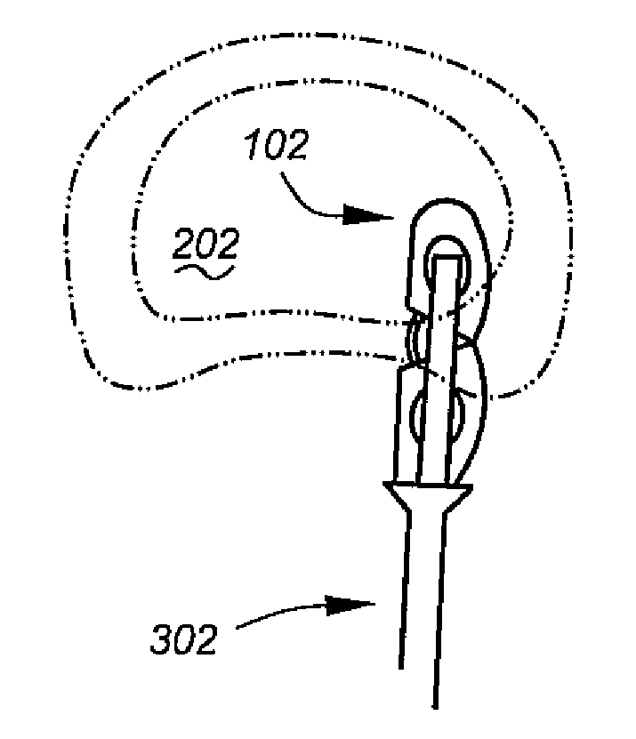
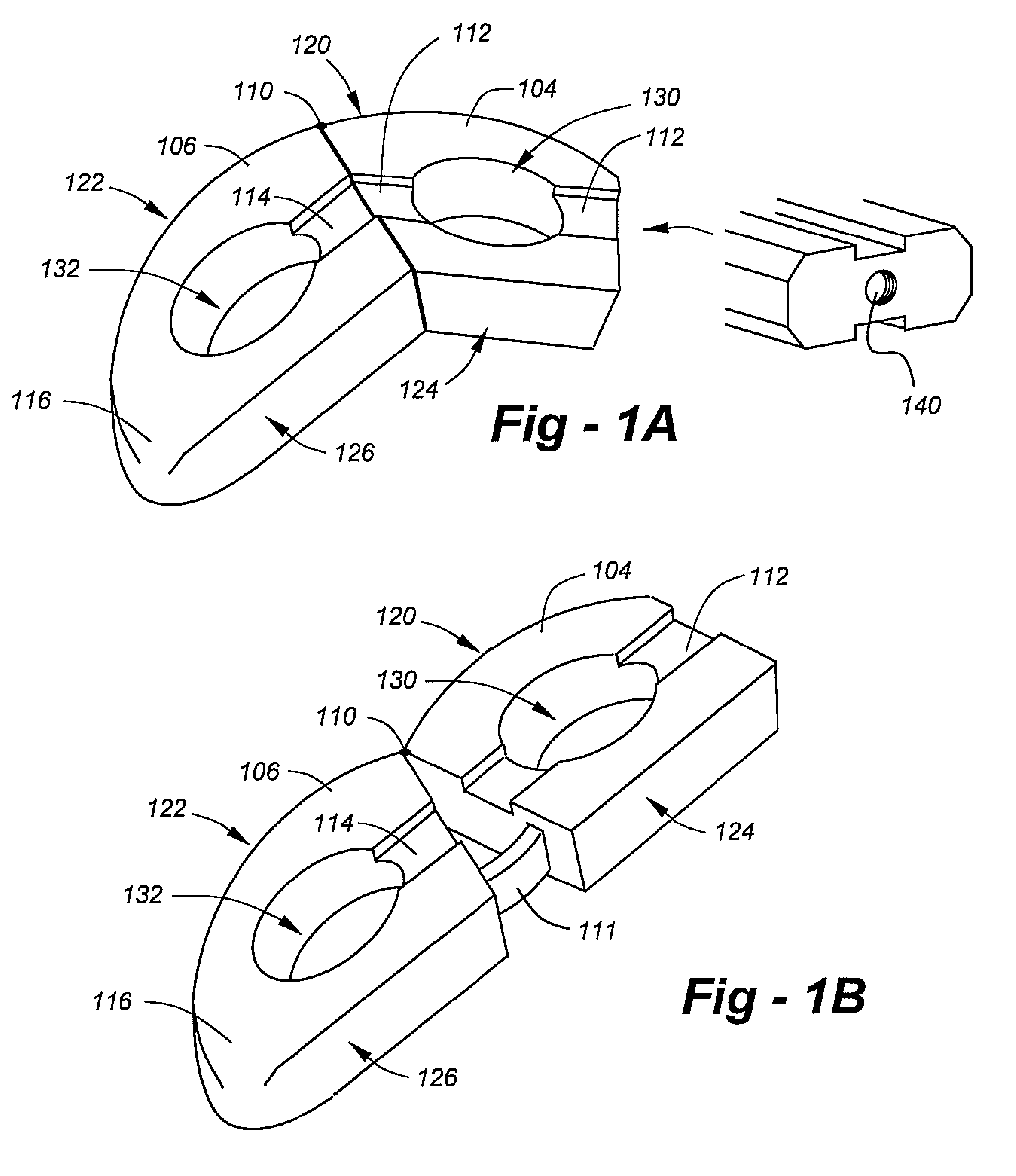
[0027] Making reference to the drawings, FIG. 1A is an oblique view of the preferred embodiment of the invention in a folded condition depicted generally at 102. The implant comprises a proximal portion 104 and a distal portion 106 joined by a hinge 110. Both portions include voids 130, 132 facilitating the introduction of bone graft and other biologic and or therapeutic substances. The proximal portion 104 includes a longitudinal recess 112, and the distal portion 106 includes a longitudinal recess 114. As shown in the end-view drawing at the right of FIG. 1A, these recesses are provided on the upper and lower surfaces of each portion. The end-view drawing also shows a central threaded hole 140 used for initial introduction.

[0028] In the preferred embodiment, the ‘outer’ surfaces 120, 122 of the respective portions 104, 106 are curved such that in the folded state of FIG. 1A a continuous outer surface is established. Although this is not necessary to the invention, curved surfaces...


PUM


Abstract

An interbody vertebral cage facilitates minimally invasive approaches to the intervertebral disc for corrective restoration of disc height, stabilization between vertebra, and fusion. The preferred embodiment provides a streamlined, slender straight contour with a central hinge or other articulating apparatus that allows the introduction of the cage into the operative field and disc space in a minimally invasive, bone-sparing manner. After partial insertion, the hinge component is activated, allowing the operator to steer the cage anterior-medially within the disc space to an anterior-central position within the intervertebral space. In this state the cage is shaped like a crescent, chevron or boomerang.

Description

REFERENCE TO RELATED APPLICATION [0001] This application claims priority from U.S. Provisional Patent Application Ser. No. 60 / 718,063, filed Sep. 16, 2005, the entire content of which is incorporated herein by reference.FIELD OF THE INVENTION [0002] This invention relates generally to intervertebral cages and, in particular, to a steerable interbody fusion cage applicable to minimally invasive surgical (MIS) procedures. BACKGROUND OF THE INVENTION [0003] One of the most common causes of chronic back pain is degenerative disc disease. The degeneration may start after a particular injury, or many occur due to multiple injuries over time. Degeneration usually takes several years. As the vertebrae grow closer, the openings in the back of the spine where the nerve roots leave the spinal canal become narrower. This can lead to pinching and irritation on the nerves, causing pain. [0004] There are many surgical approaches and methods used to fuse the spine. Most involve the placement of a b...

Claims


Application Information

Patent Timeline
Patent Type & Authority Applications(United States)
IPC IPC(8): A61F2/44
CPCA61F2/4455A61F2/4611A61F2002/30092A61F2002/30112A61F2002/30133A61F2002/30471A61F2002/30565A61F2002/3082A61F2002/4415A61F2002/4629A61F2210/0014A61F2220/0091A61F2230/0004A61F2230/0015A61F2002/2835
Inventor FALAHEE, MARK H.
Owner CTL MEDICAL CORP
Why Eureka
Try Eureka