System and method of interactively optimizing shipping density for a container

a technology of interactive optimization and shipping density, applied in the field of packaging of racked parts in containers, can solve the problems of not being able to optimize the solution, affecting the density of racks, and the investment cost of freight and containers, and the current methods are time-consuming, so as to improve the density efficiency of individual racked parts, reduce associated costs, and be convenient to us

Inactive Publication Date: 2007-03-22
FORD MOTOR CO
View PDF8 Cites 39 Cited by
  • Summary
  • Abstract
  • Description
  • Claims
  • Application Information

AI Technical Summary

Benefits of technology

[0011] One advantage of the present invention is that a system and method of interactively optimizing shipping density is provided that integrates available software tools with engineering knowledge and best practice guidelines for shipping a component part. Another advantage of the present invention is that a system and method of interactively optimizing shipping density is provided that automates the packaging planning process to improve the density efficiency of individual racked parts in a container. Still another advantage of the present invention is that a system and method of interactively optimizing shipping density is provided that reduces associated costs. A further advantage of the present invention is that a system and method of interactively optimizing shipping density is provided that analyzes a digital representation versus a physical prototype. Still a further advantage of the present invention is that a system and method of interactively optimizing shipping density is provided that is simpler to use and reduces the amount of time required to evaluate various design proposals. Yet still a further advantage of the present invention is that a system and method is provided that identifies a feature on a component that may influence packaging density, and allows for modification of the feature and evaluation of the effect of such change.
[0012] Other features and advantages of the present invention will be readily appreciated, as the same becomes better understood after reading the subsequent description taken in conjunction with the accompanying drawings.

Problems solved by technology

Therefore, any change to the configuration of a particular component part could potentially affect the rack density, as well as the freight and container investment costs.
While the current manual methods of approximating shipping density provide a solution, it may not be an optimized solution.
The current methods are time consuming and there may be inconsistencies across various product lines.

Method used


Image

  • System and method of interactively optimizing shipping density for a container
  • System and method of interactively optimizing shipping density for a container
  • System and method of interactively optimizing shipping density for a container

Examples


Embodiment Construction

)

[0018] A design for density of racked parts in a container is preferably achieved with a generic, parametric driven analytical process. Advantageously, the parametric process allows for flexibility in design and engineering analysis of the model in a fraction of the time required using conventional analytical techniques. Various computer-based tools are integrated to achieve this enormous time and expense savings, including solid modeling, parametric design, and automated studies. In this example, the process is applied to a component part for a vehicle system, although other types of systems are foreseeable. The component part design is typically generated through the use of conventional computer-aided design (CAD), including computer-aided manufacturing (CAM) and computer-aided engineering (CAE) techniques. In this example the component part is a fender.

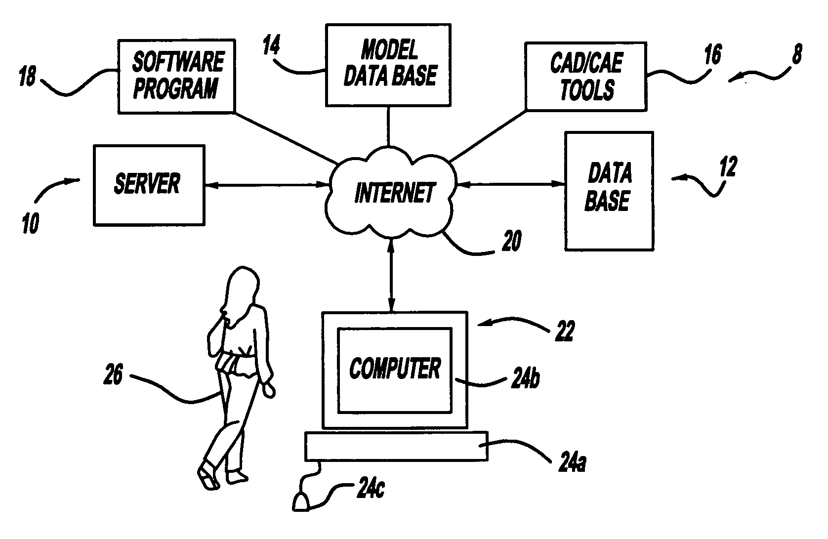
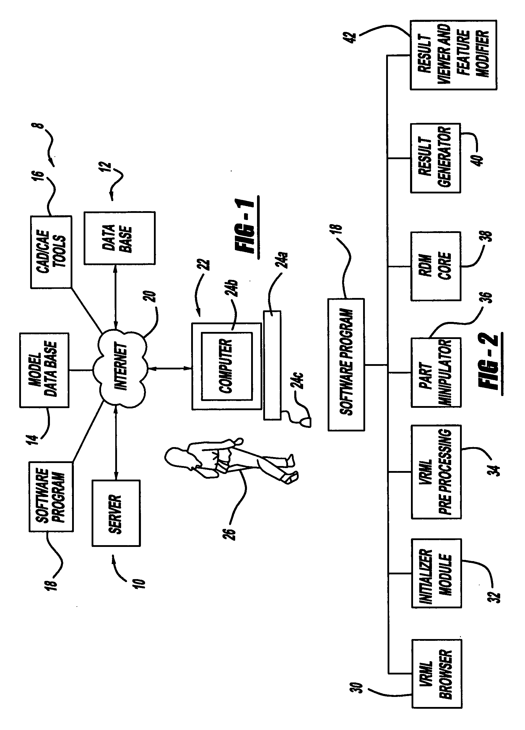
[0019] Referring to the drawings and in particular to FIG. 1, a system 8 for interactively optimizing shipping density of a com...


PUM


Abstract

A system and method for interactively optimizing shipping density of racked parts by a user is provided. The system includes a user computer system, a communications network, a remotely located computer system, a data storage device a computer-generated model of a component part; a computer-generated model of a container for transporting the component part and an executable shipping density optimization software program. The methodology includes the steps of the user selecting the component part model and container. The methodology also includes the steps of analyzing the shipping density of component parts within the container. The methodology further includes the steps of identifying a bottleneck feature and modifying the bottleneck feature and determining the optimized density of the modified component parts in the container.

Description

BACKGROUND OF THE INVENTION [0001] 1. Field of the Invention [0002] The present invention relates generally to packaging of racked parts in a container, and, more specifically, to a system and method of interactively optimizing shipping density of racked parts. [0003] 2. Description of the Related Art [0004] Manufacturers of products and especially products derived from assembled parts, frequently utilize individual parts that are fabricated at a different location than the assembly location. As a result, the individual parts are transported to the assembly location via a transport means, such as by rail, truck or air. Frequently, the parts are transported in a container. Depending on the configuration of the individual part, a number of individual parts may be placed in a rack and shipped within the container. [0005] A product, such as a vehicle, is assembled from a large number of component parts of various shapes and sizes. Most of the component parts are shipped into the assembl...

Claims


Application Information

Patent Timeline
Patent Type & Authority Applications(United States)
IPC IPC(8): G06G7/48
CPCG06Q10/04G06Q50/30G06Q10/08
Inventor DEVARAJAN, VELMURUGANANGOTTI, SERGIOTAVERNA, JENNIFERFILEV, DIMITAR
Owner FORD MOTOR CO
Why Eureka
Try Eureka