Lubricant supply device, image forming apparatus, and pressing device

a technology of image forming apparatus and lubricant supply, which is applied in the direction of rail lubrication, rail wetting/lubrication, instruments, etc., can solve the problems of solid lubricant ,/b> not being evenly pressed against the supply member, and it being extremely difficult to completely eliminate the production error in the spring

Active Publication Date: 2007-03-29
RICOH KK
View PDF12 Cites 36 Cited by
  • Summary
  • Abstract
  • Description
  • Claims
  • Application Information

AI Technical Summary

Benefits of technology

[0019] In the embodiment of the present invention described immediately above, as compared with a background pressing mechanism pressing an object to be pressed such that the biasing force of a biasing device and the pressing force pressing the object to be pressed agree, the amount of change in the pressing force pressing the object to be pressed relative to the amount of change over time in the biasing force of the biasing device is smaller, so that the amount of change over time in the pressing force when pressing the object to be pressed against a lubricant supplying target can be made smaller.

Problems solved by technology

In such a structure that both side end parts in the longitudinal direction of the solid lubricant 262 are biased with the individual springs 263, there has been a problem that the solid lubricant 262 cannot be evenly pressed against the supply member in the longitudinal direction of the solid lubricant due to unevenness in the biasing forces of the springs 263.
However, it is extremely difficult to completely eliminate the production error in the springs 263 and a difference might exist between the biasing forces of the springs 263.
Consequently, it becomes impossible to obtain a desired lubricating property.
However, the lubricant adhered on the surface of the lubricant supplying target unevenly in the longitudinal direction of the solid lubricant 262 cannot be pressed and spread sufficiently evenly only by pressing and spreading the lubricant adhered on the surface of the lubricant supplying target with the lubricant equalization blade, so that the unevenness in the lubricant cannot be sufficiently reduced.

Method used


Image

  • Lubricant supply device, image forming apparatus, and pressing device
  • Lubricant supply device, image forming apparatus, and pressing device
  • Lubricant supply device, image forming apparatus, and pressing device

Examples


Embodiment Construction

[0047] Referring now to the drawings, wherein like reference numerals designate identical or corresponding parts throughout the several views, preferred embodiments of the present invention are described.

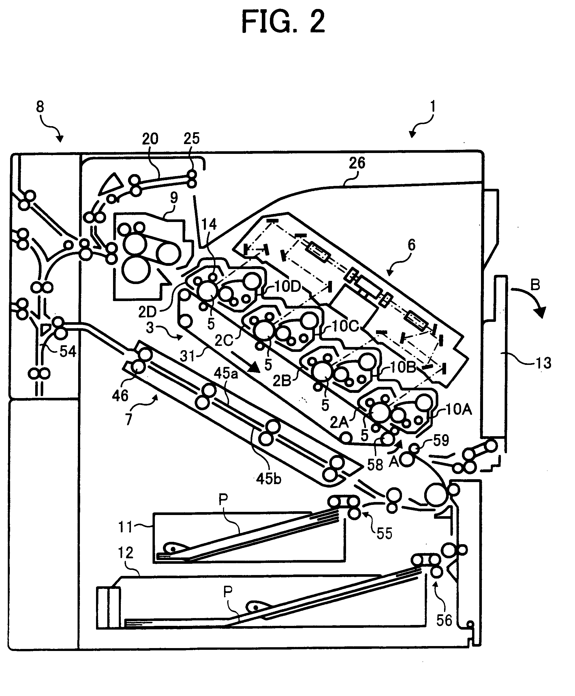
[0048]FIG. 2 is a schematic diagram illustrating an exemplary overall structure of a printer 1 as an image forming apparatus according to an embodiment of the present invention.

[0049] Image formation units 2A, 2B, 2C and 2D provided with photoconductors serving as image bearing members are installed inside of the main body of the printer 1 detachably from the main body, respectively. A transfer device 3 provided with a transfer belt 31 spanned around a plurality of rollers is arranged substantially in the center part of the main body. The transfer belt 31 is driven to rotate in the direction indicated by an arrow “A” in figure. The image formation units 2A, 2B, 2C and 2D are located above the transfer belt 31, respectively, and are arranged such that respective photoconductors 5 c...


PUM


Abstract

A lubricant supply device includes a solid lubricant, a supply member contacting and rubbing the solid lubricant and thereby scraping a lubricant off the solid lubricant and supplying the lubricant to a lubricant supplying target, and a pressing mechanism pressing the solid lubricant against the supply member. The pressing mechanism includes a biasing device, and a plurality of pressing members receiving a biasing force of the biasing device and thereby pressing places of the solid lubricant at symmetrical positions with respect to a center of a contact part of the solid lubricant contacting the supply member, respectively.

Description

BACKGROUND OF THE INVENTION [0001] 1. Field of the Invention [0002] The present invention relates to a lubricant supply device supplying a lubricant scraped off a solid lubricant by contacting and rubbing the solid lubricant to a lubricant supplying target, an image forming apparatus such as a copier, a printer, a facsimile apparatus, etc., using the lubricant supply device, and a pressing device applicable to the lubricant supply device. [0003] 2. Discussion of the Background [0004] As the lubricant supply device of this kind, for example, the one disclosed in Japanese Patent Laid-open Publication No. 2001-305907 is known. The lubricant supply device of the JP Publication includes a brush roller (a supply member) contacting a solid lubricant in a bar shape and supplying a lubricant in a powdered state, scraped off the solid lubricant by rubbing the solid lubricant, to a photoconductor belt or an intermediate transfer belt (a lubricant supplying target). The solid lubricant is held ...

Claims


Application Information

Patent Timeline
Patent Type & Authority Applications(United States)
IPC IPC(8): F16N15/00
CPCG03G2221/0005G03G21/0005G03G15/00G03G21/00
Inventor KAWAHARA, SHINICHIHARADA, HIROOMIKASUGA, TERUYUKIFUJISHIRO, TAKATSUGU
Owner RICOH KK
Why Eureka
Try Eureka