Printer
a printing machine and printing technology, applied in the field of printing machines, can solve the problems of broken optical disks and damage to the cutter mechanism itself, and achieve the effect of preventing the rigid recording medium from being damaged and preventing the cutter from being malfunctioning
- Summary
- Abstract
- Description
- Claims
- Application Information
AI Technical Summary
Benefits of technology
Problems solved by technology
Method used
Image
Examples
first embodiment
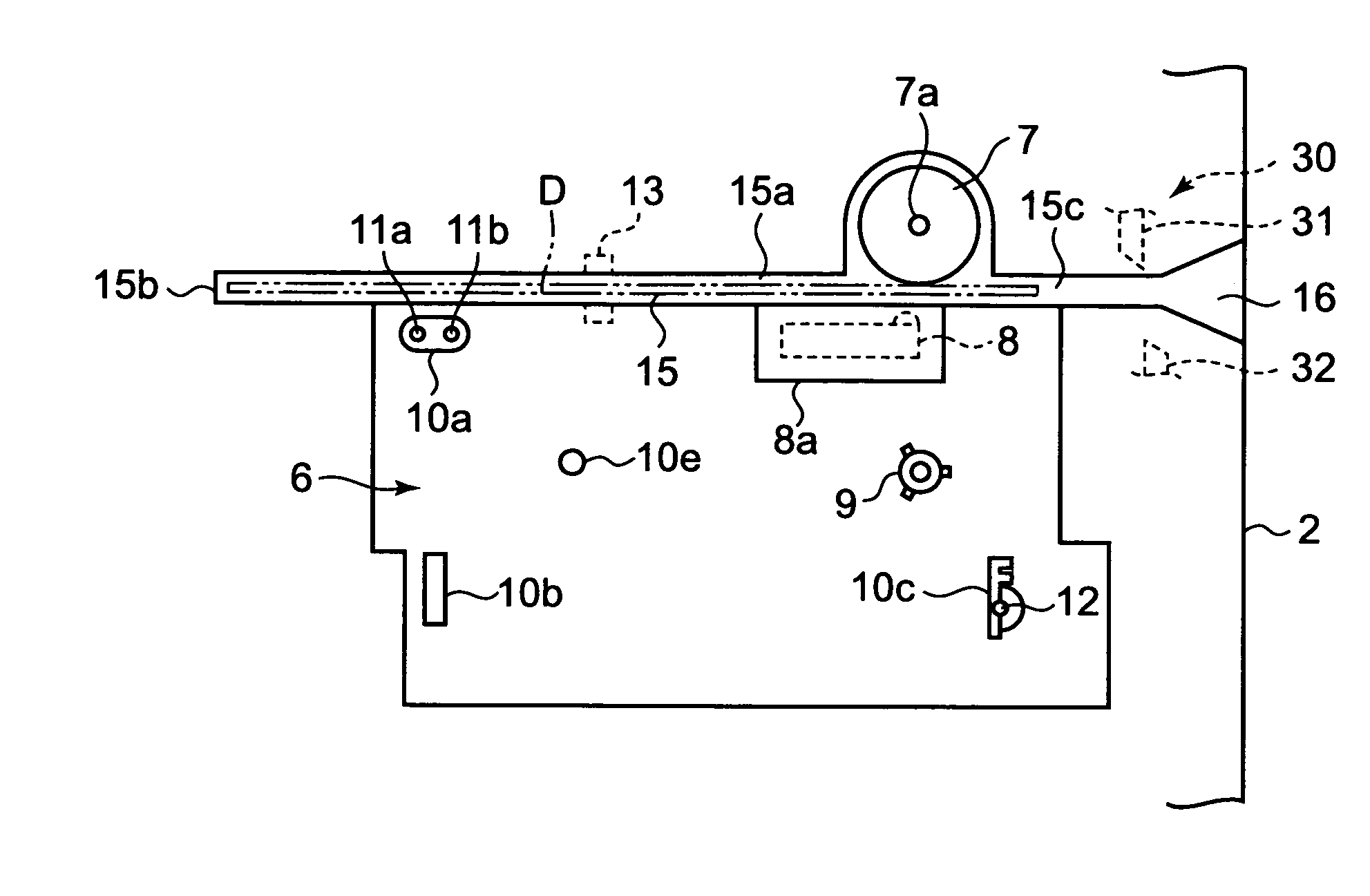
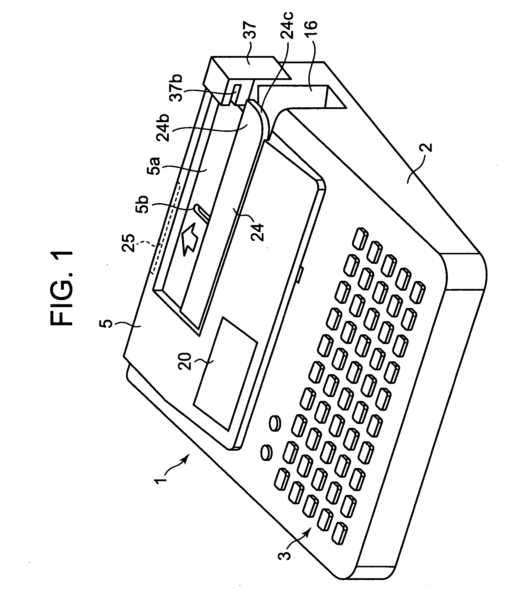
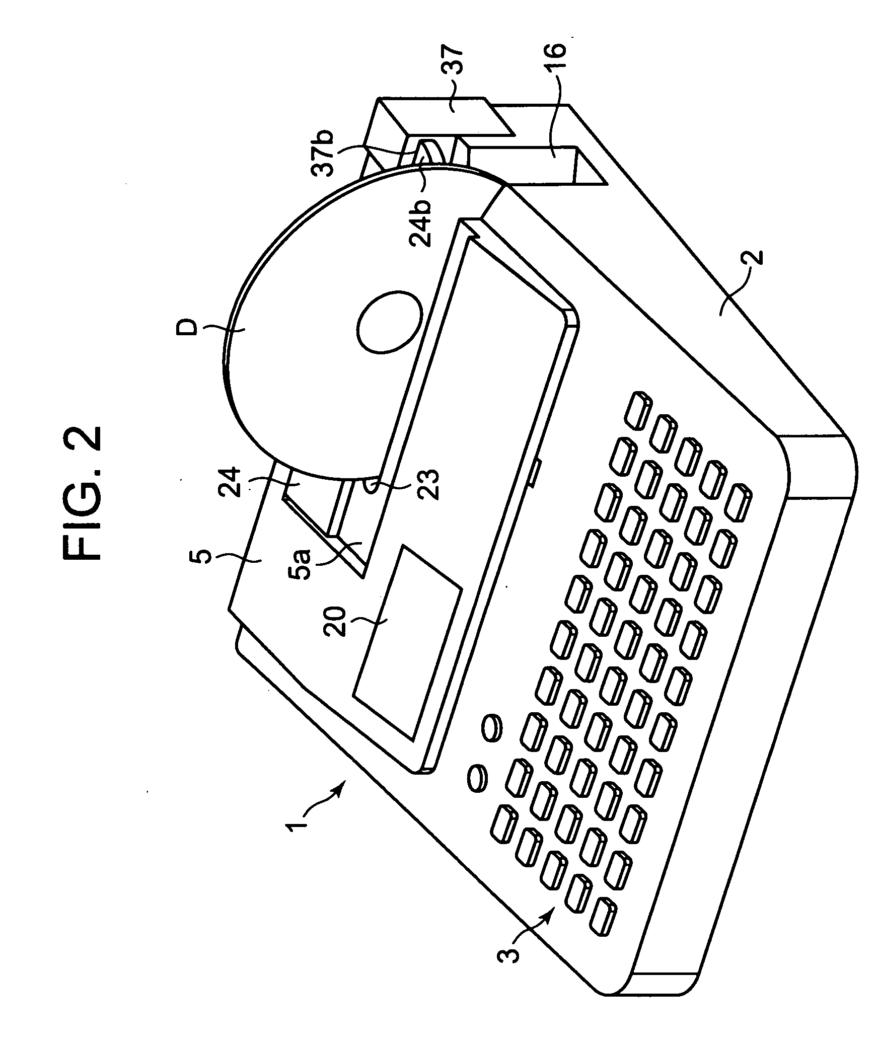
[0072] Embodiments and modifications of the present invention will be described with reference to the accompanying drawings. FIG. 1 is a perspective view of a printer according to the present invention. FIG. 2 is a perspective view of the FIG. 1 printer with an optical disk set in the printer. FIG. 3 is a perspective view of the printer with a cover open. FIG. 4 is a plan view indicative of an internal structure of the printer.
[0073] The printer should print directly on a label (or printing) face of a disk-like rigid recording medium (or optical disk) such as a data recordable CD-R (Compact Disk-recordable) or a DVD-R (Digital Versatile Disk-Recordable) and also print on a soft tape-like printing medium (or printing tape).
[0074] The printer comprises a printer body 1 having a body case 2 and a cover 5. A key-in unit 3 and a display 4 provided on an upper surface of the body case 2. The key-in unit 3 comprises character keys for inputting character string data to be printed, a print...
second embodiment
[0106] In this second embodiment, as shown in FIG. 11, when the optical disk D is inserted upstanding into the printer body 1 from its open end 16, the optical disk D hits the inclined edge 24c of the inlet cover 24, which moves the inlet cover 24 against the resiliency of the spring 43 backward on the printer body 1 to a position where the inlet cover 24 overlaps at its right-hand end with the upper end of the cutter button 37, thereby covering the cutter button 37, as shown in FIGS. 11 and 12B. Thus, the user cannot manually press the cutter button 37 down and hence operate the cutter 30.
[0107] When the optical disk D is printed and then taken out of the printer body 1, and more particularly, the open end 23, the inlet cover 24 is moved forward on the printer body 1 by the resiliency of the spring 43, which causes the engaging end 24b of the inlet cover 24 to move away from above the cutter button 37, thereby exposing the top of the cutter button 37 and causing the inlet cover 24 ...
third embodiment
[0114] As described above, according to the printer of the third embodiment, when in disk printing the inlet cover 24 is moved manually backward on the printer body 1 to open the inlet 23, the cutter button 37 is locked by the engaging end 24b of the inlet cover 24, thereby disabling the cutter 30. Thus, when the optical disk D is printed in the printer body 1, the movable blade 32 does not operate, thereby damaging no optical disk even when the cutter button 37 is advertently pushed down manually.
[0115]FIGS. 16-18 show a fourth embodiment in which as in the second embodiment the cutter button 37 is movable vertically relative to the body case 2. The cutter button 37 is elastically pushed upward by a compression spring 38 such that the cutter button 37 is flush with the body case 2. As in the third embodiment the inlet cover 24 is received manually slidable back and forth within a recess 5a of the cover 5 on the printer body 1. A manual knob 24d is provided at the midpoint of the le...
PUM
 Abstract
Description
Claims
Application Information
 - R&D
- Intellectual Property
- Life Sciences
- Materials
- Tech Scout
- Unparalleled Data Quality
- Higher Quality Content
- 60% Fewer Hallucinations
Browse by: Latest US Patents, China's latest patents, Technical Efficacy Thesaurus, Application Domain, Technology Topic, Popular Technical Reports.
© 2025 PatSnap. All rights reserved.Legal|Privacy policy|Modern Slavery Act Transparency Statement|Sitemap|About US| Contact US: help@patsnap.com


