
Radiographic image processing apparatus for processing radiographic image taken with radiation, method of radiographic image processing, and computer program product therefor

a radiographic image and processing apparatus technology, applied in the field of radiographic image processing apparatus for processing radiographic image taken with radiation, can solve the problems of dim outline of the material body included in the image, worsening the visibility of the small material body, and displaying the afterimage of the moving material body

Inactive Publication Date: 2007-03-29
KK TOSHIBA
View PDF5 Cites 16 Cited by
  • Summary
  • Abstract
  • Description
  • Claims
  • Application Information

AI Technical Summary

Benefits of technology

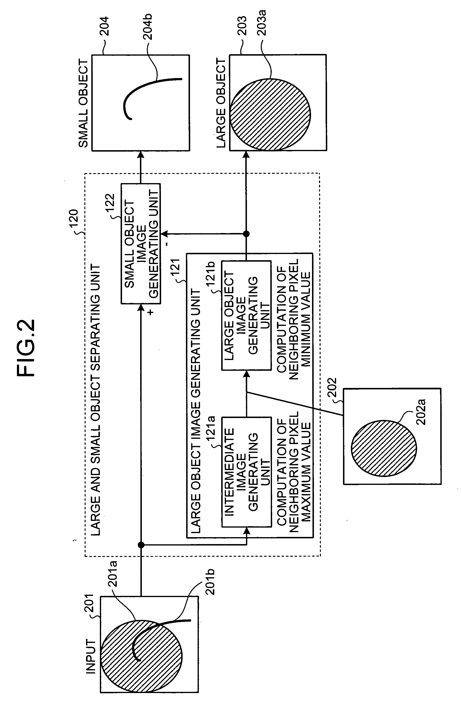
The present invention is a radiographic image processing apparatus and method that can generate an intermediate image, a large object image, and a small object image from a radiographic image. The apparatus includes a radiographic image inputting unit, an intermediate image generating unit, a large object image generating unit, and a small object image generating unit. The method involves inputting a radiographic image, generating an intermediate image by computing a maximum pixel value, generating a large object image by computing a minimum pixel value, and generating a small object image by computing difference. The technical effect of this invention is to provide a more efficient and accurate way to process radiographic images, which can be useful in medical diagnosis and treatment.

Problems solved by technology

Generally, in the spatial smoothing, there is a drawback that material body included in the image has a dim outline.
In the temporal smoothing, there is a drawback that an afterimage of the moving material body is displayed.
H06-154200, however, since the spatial smoothing is performed to the region including the moving material body, there is a problem that the visibility is worsened for the small material body.
For example, there is a problem that a doctor manipulating the radiation diagnosis apparatus has difficulty in seeing a small moving medical tool such as a guide wire, which the doctor is required to particularly-clearly confirm, since such a small tool appears only with a dim outline.

Method used


Image

  • Radiographic image processing apparatus for processing radiographic image taken with radiation, method of radiographic image processing, and computer program product therefor
  • Radiographic image processing apparatus for processing radiographic image taken with radiation, method of radiographic image processing, and computer program product therefor
  • Radiographic image processing apparatus for processing radiographic image taken with radiation, method of radiographic image processing, and computer program product therefor

Examples


first embodiment

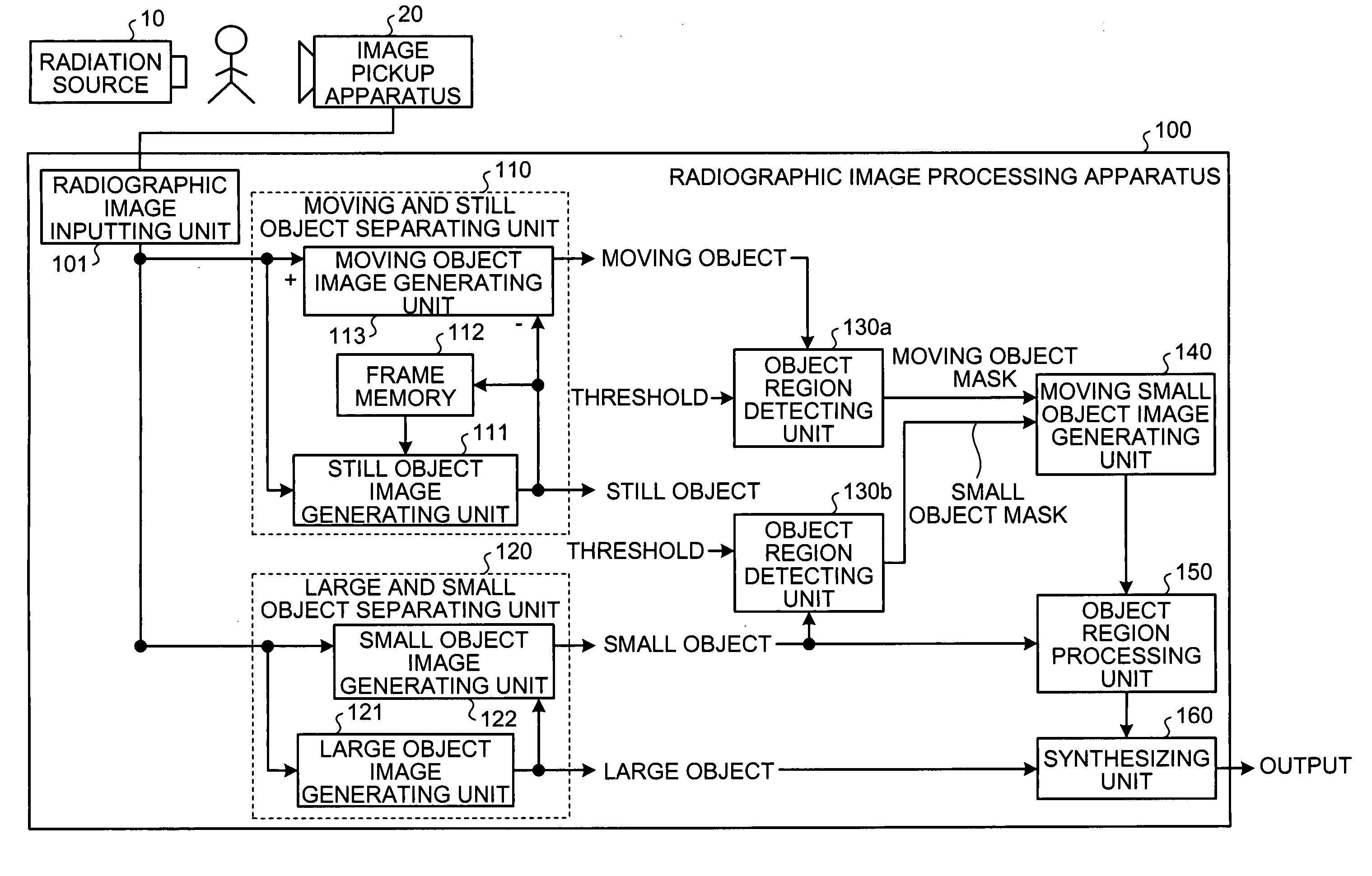
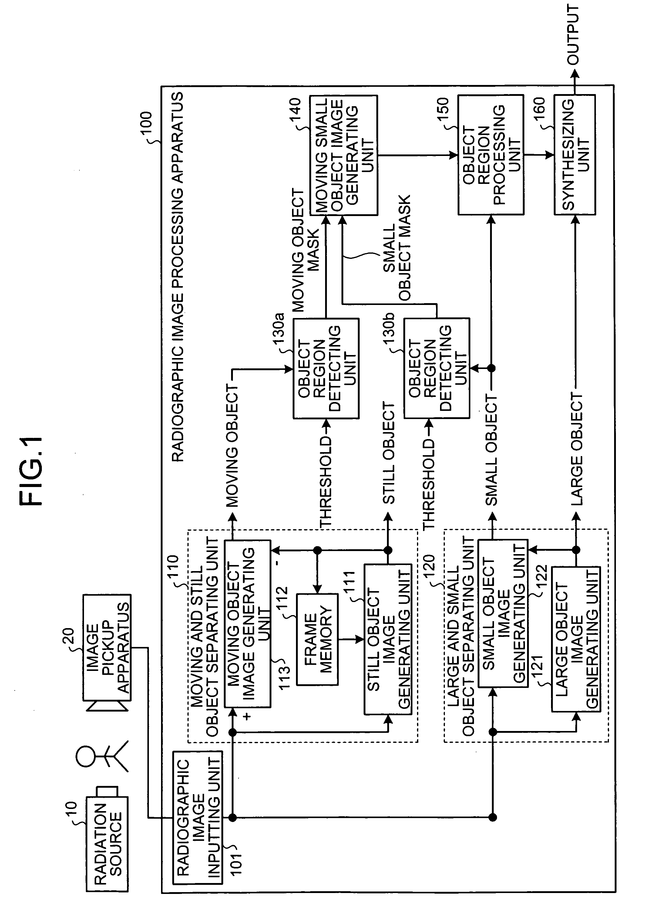
[0022] In a radiographic image processing apparatus according to the present invention, a separation process of separating a large object which is larger than an object having a predetermined size from a small object which is an object other than the large object and a separation process of separating a moving object which is a moving material body from a still object which is a still material body are concurrently performed, a moving small object which is a small object in motion is computed by synthesizing the small object and the moving object, and the visibility improving process is performed to the computed moving small object.

[0023]FIG. 1 is a block diagram showing a configuration of a radiographic image processing apparatus 100 of the first embodiment. As shown in FIG. 1, the radiographic image processing apparatus 100 is connected to an image pickup apparatus 20 to perform image processing on a radiographic image (input image) supplied from the image pickup apparatus 20.

[00...

second embodiment

[0106] Therefore, in a radiographic image processing apparatus according to the invention, the large object and the small object are first separated, and the moving object and still object separation process is performed to the separated small object. The visibility improving process is performed to the moving small object (moving object separated from small object) separated in the above manner.

[0107]FIG. 9 is a block diagram showing a configuration of a radiographic image processing apparatus 900 of the second embodiment. As shown in FIG. 9, the radiographic image processing apparatus 900 includes a moving and still object separating unit 910, the large and small object separating unit 120, an object region detecting unit 930, an object region processing unit 950, and a synthesizing unit 960.

[0108] The second embodiment differs from the first embodiment in the images input to a still object image generating unit 911, a moving object image generating unit 913, the object region de...


PUM


Abstract

A radiographic image processing apparatus includes a radiographic image inputting unit, an intermediate image generating unit, a large object image generating unit, and a small object image generating unit. The radio graphic image inputting unit inputs a radiographic image which is a frame of moving picture taken radiographically. The intermediate image generating unit generates an intermediate image whose pixel value is a maximum pixel value of pixels within each area of a first size in a radiographic image. The large object image generating unit generates a large object image whose pixel value is a minimum pixel value of pixels within each area of a second size in the intermediate image. The small object image generating unit generates a small object image whose pixel value is a difference between pixel value of the radiographic image and pixel value of the large object image corresponding to each pixel of the radiographic image.

Description

CROSS-REFERENCE TO RELATED APPLICATIONS [0001] This application is based upon and claims the benefit of priority from the prior Japanese Patent Application No. 2005-281980, filed on Sep. 28, 2005; the entire contents of which are incorporated herein by reference. BACKGROUND OF THE INVENTION [0002] 1. Field of the Invention [0003] The present invention relates to a radiographic image processing apparatus that processes a radiographic image taken with radiation, a method of radiographic image processing, and a computer program product therefor. [0004] 2. Description of the Related Art [0005] Conventionally, in order to improve visibility of a moving image displayed in a radiation diagnosis apparatus, a noise reduction process is performed by spatial smoothing in which the smoothing is performed between adjacent pixels in the same image or by temporal smoothing in which the smoothing is performed among the pixels corresponding to the plural continuous images. [0006] Generally, in the s...

Claims


Application Information

Patent Timeline
Patent Type & Authority Applications(United States)
IPC IPC(8): G06K9/00
CPCA61B6/486A61B6/5217G06T5/009G06T2207/30004G06T7/2053G06T2207/10116G06T2207/20032G06T7/2006G06T7/215G06T7/254G16H50/30G06T5/92
Inventor NONAKA, RYOSUKEITOH, GOH
Owner KK TOSHIBA
Learn More