Milling cutter, a milling cutter body and an indexable cutting insert

a technology of indexable cutting inserts and milling cutters, which is applied in the field of milling, can solve the problem of limited cutting depth to the length of the main cutting edge, and achieve the effect of great cutting depth

Inactive Publication Date: 2007-03-29
SECO TOOLS AB
View PDF14 Cites 49 Cited by
  • Summary
  • Abstract
  • Description
  • Claims
  • Application Information

AI Technical Summary

Benefits of technology

[0004] It is desirable to provide a milling cutter and indexable cutting inserts adapted thereto, th

Problems solved by technology

A drawback that this known milling cutter has is that the cutting depth is limited to the length of the main cutting edge since the minor cutting edge

Method used


Image

  • Milling cutter, a milling cutter body and an indexable cutting insert
  • Milling cutter, a milling cutter body and an indexable cutting insert
  • Milling cutter, a milling cutter body and an indexable cutting insert

Examples


Embodiment Construction

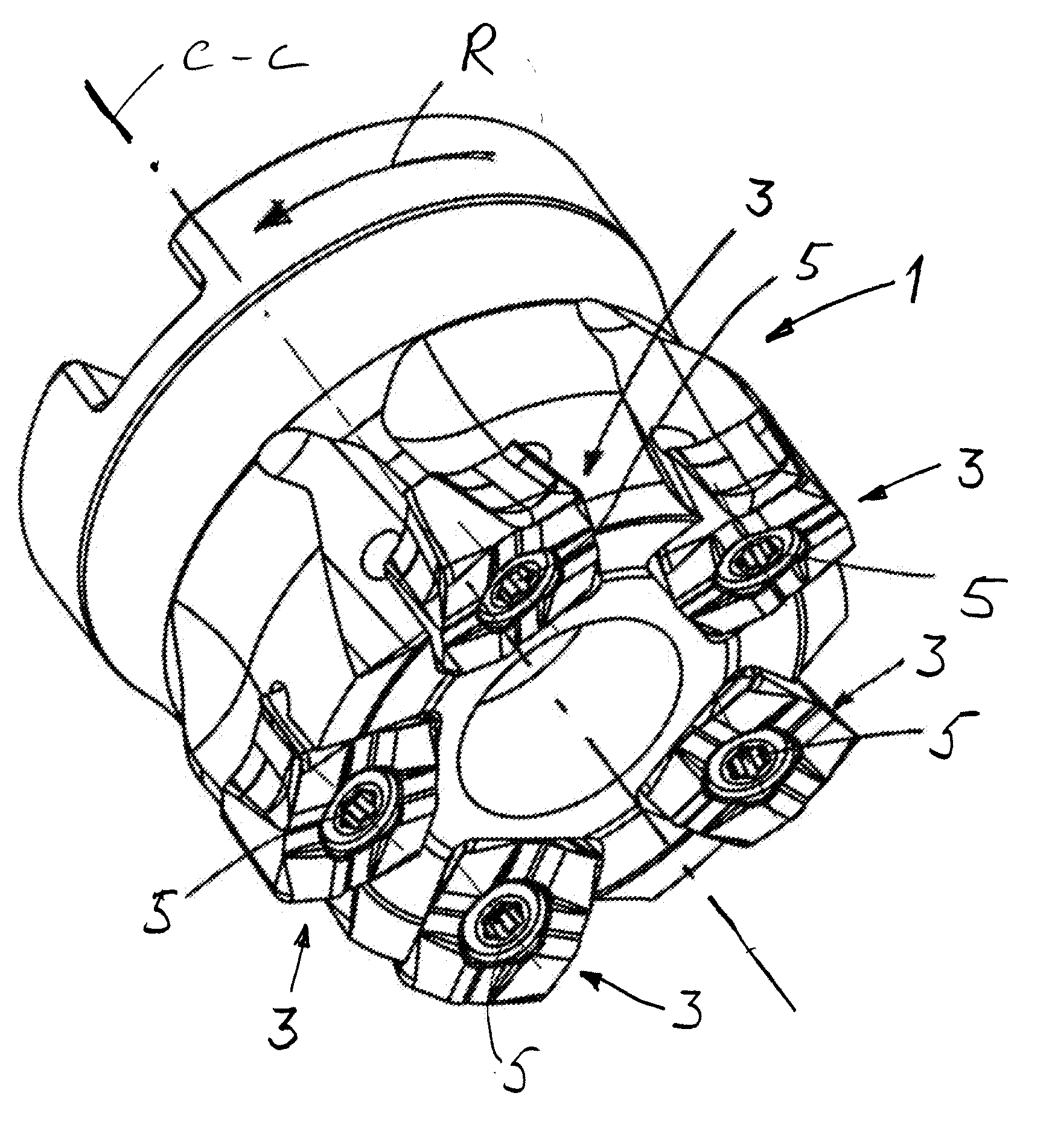
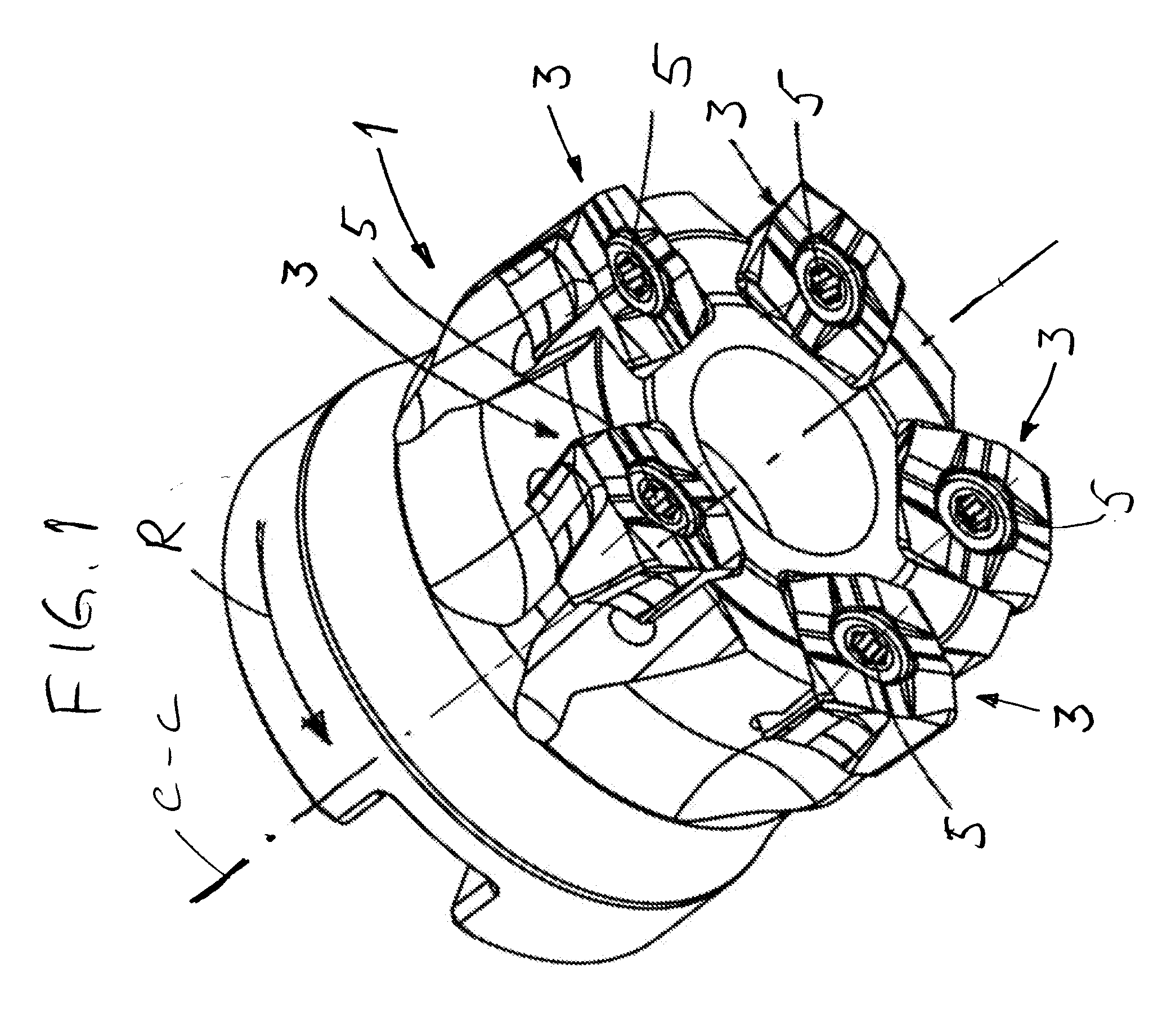
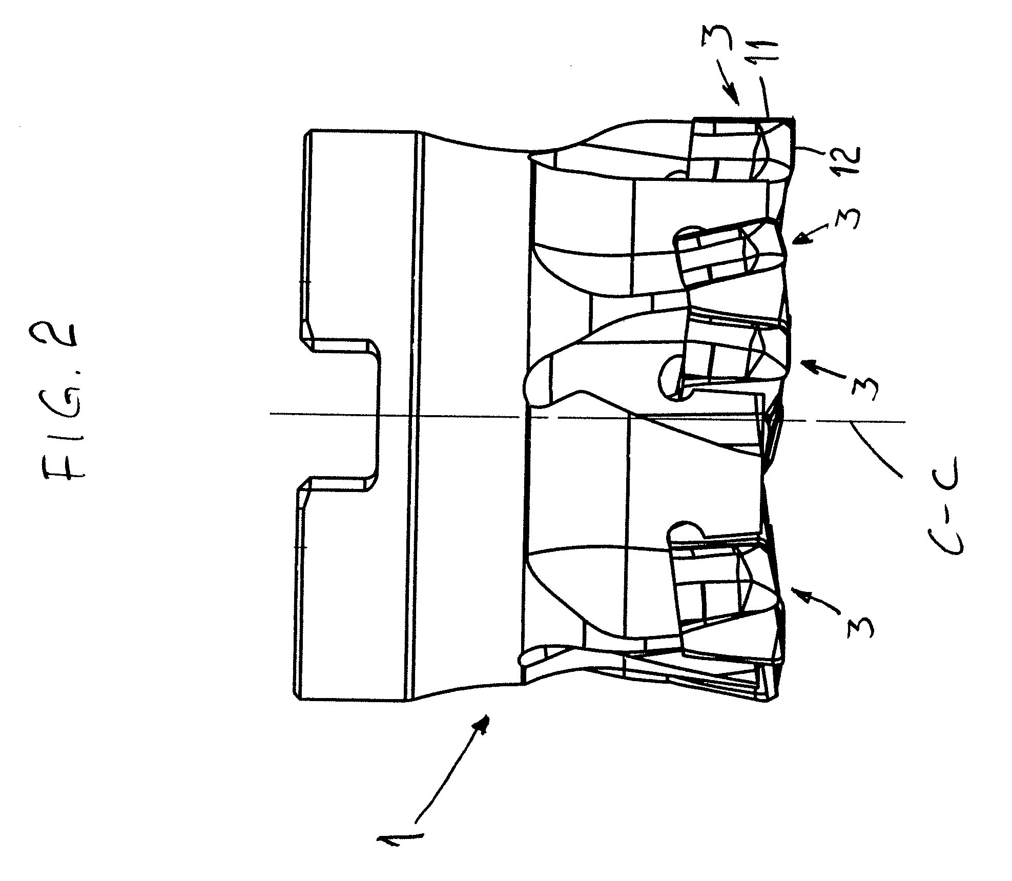
[0022] The milling cutter according to the present invention shown in FIGS. 1 and 2 comprises a milling cutter body 1, which has a number of cutting insert seats at the forwardly facing end in FIG. 1, in which a corresponding number of indexable cutting insert 3 are received. Each indexable cutting insert 3 has a center hole 4 and is secured in an associated cutting insert seat by means of a center screw 5 received by the center hole 4. In FIG. 1 the center axis C-C of the milling cutter is drawn, the center axis C-C also defining the axis of rotation of the milling cutter and its axial direction. The rotational direction R of the milling cutter is depicted with an arrow in FIG. 1.

[0023] The center screws 5 extend along the axial direction of the milling cutter, however the center screws 5 are not parallel with the rotational axis C-C. The indexable cutting inserts 3 are consequently tangentially mounted in the milling cutter body 1.

[0024] The milling cutter body 1 is formed for c...


PUM

PropertyMeasurementUnit
Thicknessaaaaaaaaaa
Shapeaaaaaaaaaa

Abstract

A milling cutter for chip removing machining includes a milling cutter body with a number of cutting insert seats in connection to a chip removing end of the milling cutter body, the milling cutter body being formed to cooperate with a tool attachment at its opposite end in the axial direction, wherein indexable cutting inserts are secured in the cutting insert seats, each the indexable cutting insert having a top surface and a bottom surface substantially parallel with the top surface, wherein side surfaces extend between the top surface and the bottom surface, the indexable cutting insert having the basic shape of a truncated pyramid. The invention also relates to a milling cutter body and an indexable cutting insert, per se. Each indexable cutting insert has its top surface facing against the chip removing end of the milling cutter, and main cutting edges of the indexable cutting insert extend from the top surface of the indexable cutting insert.

Description

BACKGROUND AND SUMMARY [0001] The present invention generally relates to a milling cutter for chip removing machining, a milling cutter body and an indexable cutting insert that is intended to be mounted to a milling cutter body. [0002] A milling cutter is previously known, which comprises a milling cutter body that is provided with a number of indexable cutting inserts. Each indexable cutting insert comprises a number of main cutting edges and a minor cutting edge associated with each major cutting edge. A minor cutting edge forms a right angle with an associated major cutting edge. This known milling cutter is especially intended for milling of right-angled corners in a work piece. A drawback that this known milling cutter has is that the cutting depth is limited to the length of the main cutting edge since the minor cutting edge on same edge as the cutting insert is situated radially outside of the main cutting edge when the cutting insert is mounted on the milling cutter body. [...

Claims


Application Information

Patent Timeline
IPC IPC(8): B23C5/00
CPCB23B27/16B23C5/06B23C5/202B23C2200/087Y10T407/1932B23C2200/205Y10T407/1924Y10T407/1908Y10T407/23B23C2200/125B23C2200/326B23B27/164B23C5/20
Inventor AGIC, ADNAN
Owner SECO TOOLS AB
Why Eureka
Try Eureka