Waterproof/drainage structure for a casing, and electronic devices

a casing and water-drainage technology, applied in the direction of casings/cabinets/drawer details, contact mechanisms, instruments, etc., can solve the problems of difficulty in discharge such water or dust to the outside, and difficulty in removing water or dust from the outside, so as to prevent the stroke of the pushbuttons and prevent the deterioration of the operability of the pushbuttons. , the effect of efficien

Inactive Publication Date: 2007-04-05
FUJITSU LTD
View PDF12 Cites 55 Cited by
  • Summary
  • Abstract
  • Description
  • Claims
  • Application Information

AI Technical Summary

Benefits of technology

[0010] The present invention has been made in view of the problem described above, and therefore it is an object of the present invention to provide a waterproof / drainage structure for a casing and an electronic device, which make it possible to efficiently discharge water, dust, or the like that has entered a space between a cover member of the casing and a sheet portion retaining pushbuttons.
[0029] Accordingly, it is possible to prevent the stroke of the pushbuttons from being hindered by mold occurring due to water entering the space between the cover member and the button unit, dust, or the like, thereby preventing a deterioration in the operability of the pushbuttons.

Problems solved by technology

However, in the conventional casing waterproofing techniques, water, dust, or the like entering the space between the casing and the sheet portion retaining the pushbuttons is scattered and deposited over a wide area of the sheet portion, making it difficult to discharge such water or dust to the outside.
Water, dust, or the like rarely exerts an adverse influence on internal electronic devices even when it remains in the space between the casing and the sheet portion.
However, there is a fear that the stroke of the pushbuttons may be hindered by mold occurring due to the water remaining in the interior, dust, or the like, leading to a deterioration in the operability of the pushbuttons.

Method used


Image

  • Waterproof/drainage structure for a casing, and electronic devices
  • Waterproof/drainage structure for a casing, and electronic devices
  • Waterproof/drainage structure for a casing, and electronic devices

Examples


first embodiment

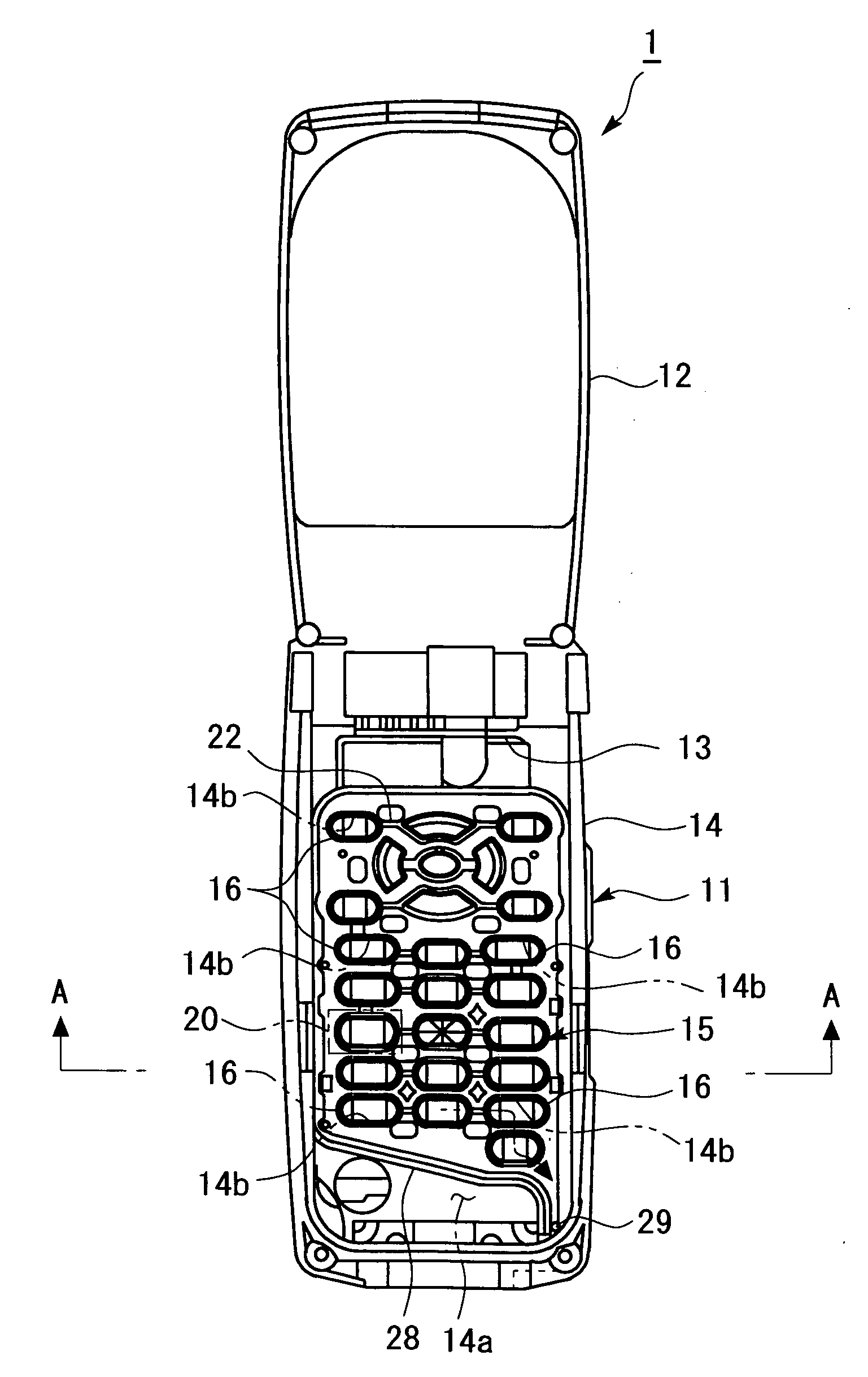
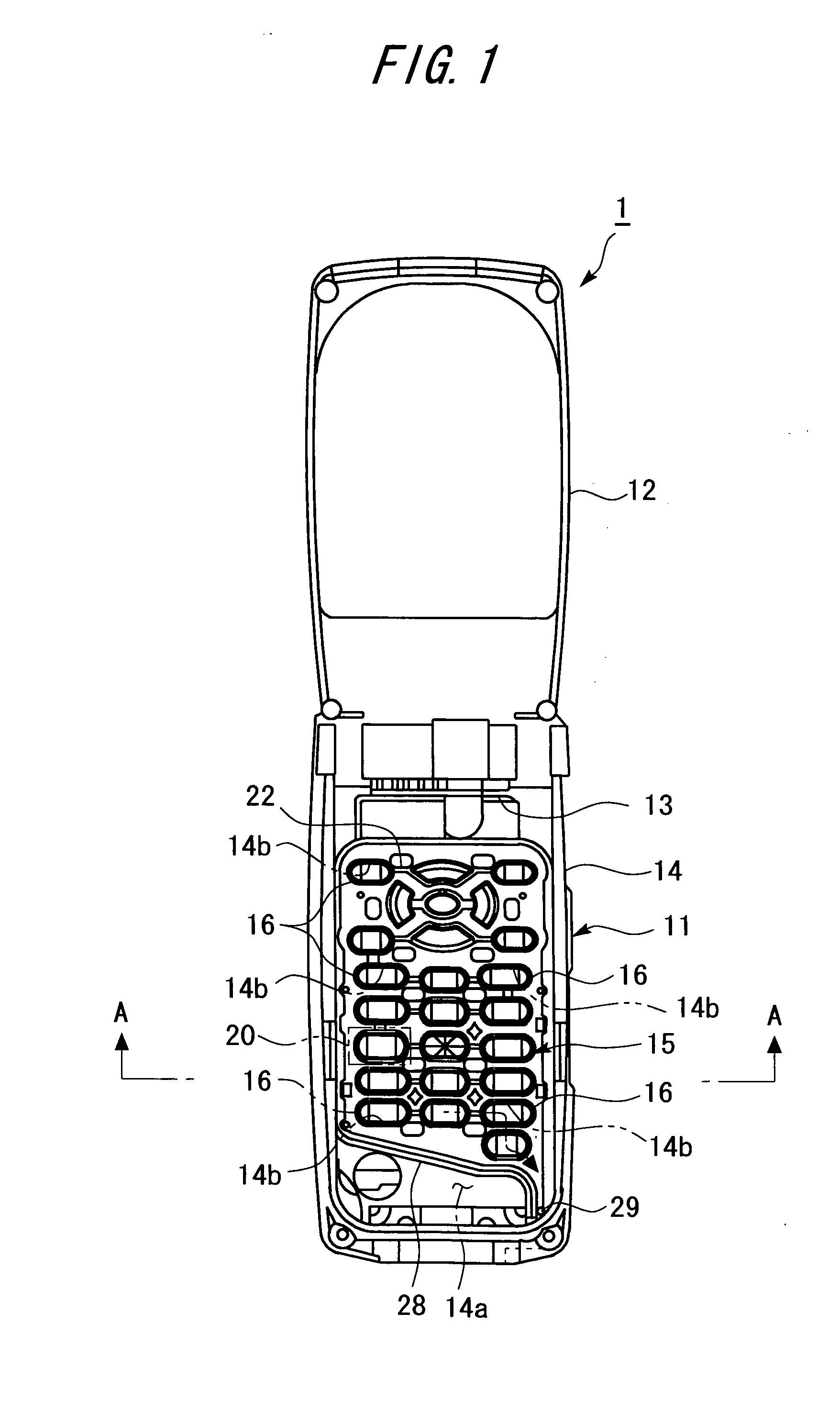
[0048]FIG. 1 shows a portable telephone 1 as an electronic device according to the present invention. The portable telephone 1 has a lower casing 11 and an upper casing 12 which are substantially rectangular and flat. One longitudinal ends of the lower casing 11 and upper casing 12 are connected to each other by devices of a hinge 13 so as to freely open and close.

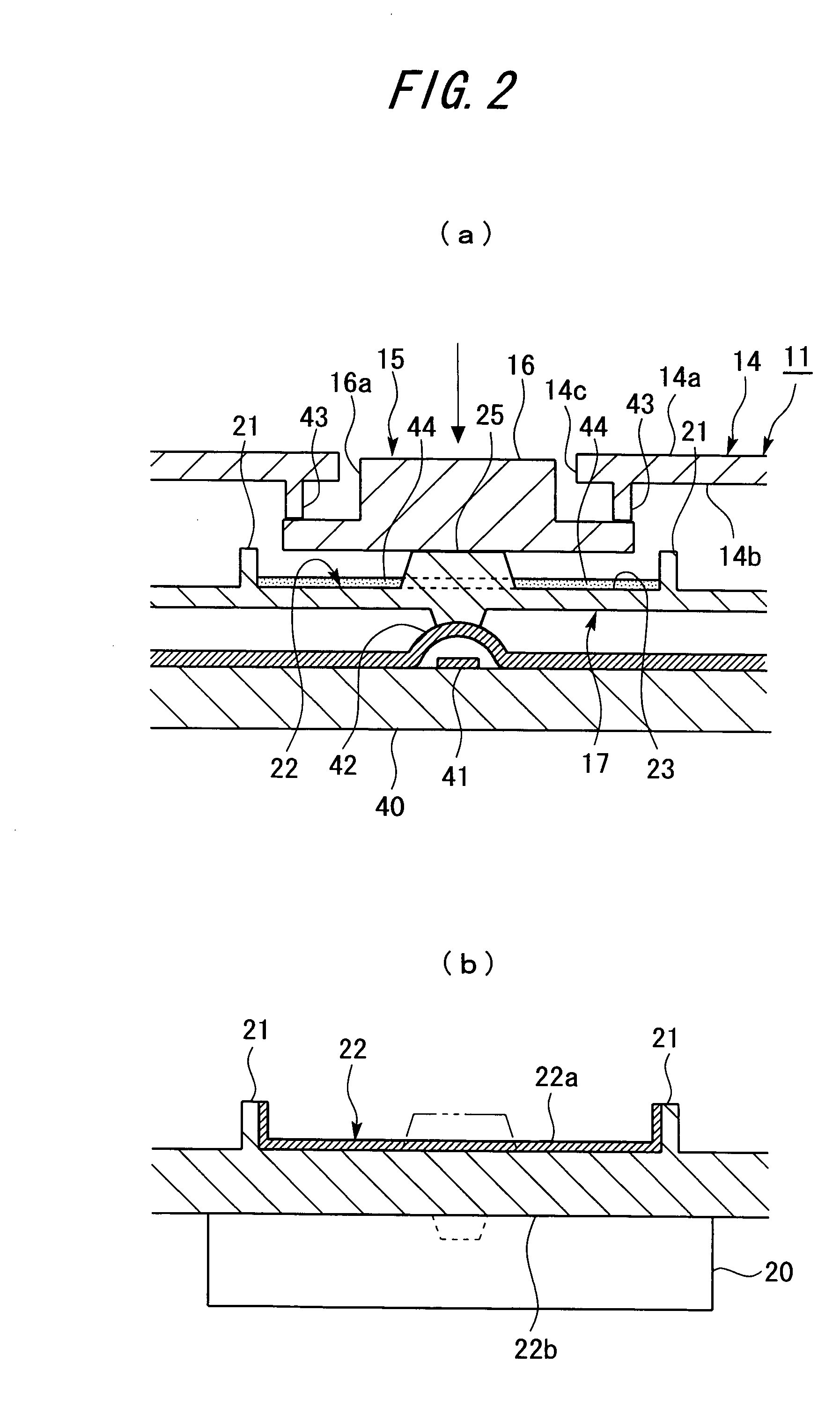
[0049] It should be noted that FIG. 1 shows a state in which an upper surface portion 14a (see FIG. 2(a)) of a cover member 14 in the lower casing 11 is removed, thus leaving a button unit 15 exposed.

[0050] A vibrator 20 as a vibrating member is provided inside the lower casing 11. The vibrator 20 abuts a bottom wall portion 22b (see FIG. 2(b)) of a drainage channel 22 in the sheet portion 17 of the button unit 15.

[0051] Further, the same circuit substrate, electronic components, and the like as those of an ordinary portable telephone are provided inside the lower casing 11. It should be noted that those circuit substrat...

third embodiment

[0103]FIG. 13 shows a sheet portion 17 according to the present invention. The sheet portion 17 is provided with a plurality of drainage channels 22. The drainage channels 22 have a plurality of wide channel portions 23 (not shown) opposed to part of all the pushbuttons 16. Further, each drainage channel 22 is formed such that the path connecting its wide channel portions 23 and connection channel portions 24 can be drawn in one stroke.

[0104] A channel outlet 26 is provided at one end of each drainage channel 22. Further, the sheet portion 17 is provided with drainage holes 29 corresponding to the respective channel outlets 26. The water storage tank 33 is provided with a plurality of inlets 33a. Further, each of the plurality of the drainage holes 29 is connected to one of the inlets 33a of the water storage tank 33.

[0105] Further, as shown in FIG. 14, a check valve 35 is provided at each of the plurality of inlets 33a of the water storage tank 33.

[0106] Since the plurality of dr...

fourth embodiment

[0108]FIG. 15 shows a substrate 51 and a button unit 15 in an electronic device 50 according to the present invention. The substrate 51 is provided with a heat generating component 52 such as a central processing unit (CPU). A sheet portion 17 of the button unit 15 is arranged above the heat generating component 52.

[0109] As shown in FIG. 16, the sheet portion 17 arranged above the heat generating component 52 is provided with a drainage channel 53 that is the same as the drainage channel 22 of the first embodiment. That is, the drainage channel 53 is formed in the sheet portion 17 in the form of a groove. Further, as in the first embodiment, the drainage channel 53 has wide channel portions and connection channel portions. A bottom wall portion 53a of the drainage channel 53 is in abutment with the heat generating component 52.

[0110] In the electronic device 50, the heat generating component 52 is cooled with water 44 flowing in the drainage channel 53. Accordingly, there is no ne...


PUM


Abstract

Provided is a waterproof / drainage structure for a lower casing 11 having a plurality of pushbuttons 16 on a surface thereof. The waterproof / drainage structure has a cover member 14 forming the surface and provided with a plurality of button holes 14a, the plurality of pushbuttons 16, and a sheet portion 17 retaining the plurality of pushbuttons 16 at predetermined positions. The waterproof / drainage structure includes a button unit 15, in which the sheet portion 17 is arranged along a back surface 14b of the cover member 14 and in which an outer peripheral portion of the sheet portion 17 is held in close contact with the cover member 14, with the pushbuttons 16 being inserted in button holes 14c of the cover member 14. The sheet portion 17 is provided with a groove-like drainage channel 22 having a channel portion that is opposed to each of the pushbuttons 16 and is larger than a surface area within a maximum outer periphery of the pushbuttons 16.

Description

BACKGROUND OF THE INVENTION [0001] 1.<<Field of the invention>>[0002] The present invention relates to a waterproof / drainage structure for a casing which is suitably used for electronic devices and the like having a pushbutton such as a notebook PC, a portable telephone, a transceiver, an electric reel, kitchenware, and a doorbell, and to an electronic device using the same. [0003] 2.<<Description of the Related Technology>>[0004] In recent years, various functions are required of electronic devices relating to Information Technology (IT), such as a portable telephone and a personal computer. Of those, one of the functions frequency demanded by users is the waterproof function for the area around a pushbutton. [0005] Conventionally, there have been proposed various techniques waterproofing the area around a pushbutton of an electronic device. For example, there has been proposed a key pad for waterproof appliance which retains: a sheet portion affixed onto th...

Claims


Application Information

Patent Timeline
Patent Type & Authority Applications(United States)
IPC IPC(8): E04B1/70
CPCG06F3/0202H01H2213/008H04M1/18H04M1/23H04M1/02H05K5/02
Inventor YAMAGUCHI, SHINGOCHOURAKU, KOHEI
Owner FUJITSU LTD
Why Eureka
Try Eureka