Multi-axes inker

a multi-axis, ink technology, applied in the direction of printing presses, electrical devices, printing, etc., can solve the problem that the ink is marked at the wrong die, and achieve the effect of reducing the probability of error, efficient and correct marking of the ink in the defective di

Inactive Publication Date: 2007-04-05
KING YUAN ELECTRONICS
View PDF1 Cites 5 Cited by
  • Summary
  • Abstract
  • Description
  • Claims
  • Application Information

AI Technical Summary

Benefits of technology

[0006] The purpose of the present invention is to provide a multi-axes inker used to efficiently and correctly mark the ink in the defective die. Therefore, the probability of error can be reduced.

Problems solved by technology

However, the conventional inker will mark at the wrong die because the inker is not stable and will move back and forth.

Method used


Image

  • Multi-axes inker
  • Multi-axes inker
  • Multi-axes inker

Examples


Embodiment Construction

[0010] The detailed description of the present invention will be discussed in the following embodiments, which are not intended to limit the scope of the present invention, but can be adapted for other applications. While drawings are illustrated in details, it is appreciated that the quantity of the disclosed components may be greater or less than that disclosed, except expressly restricting the amount of the components.

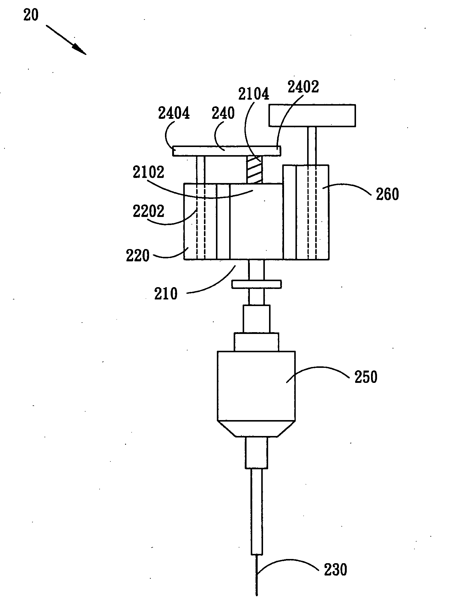
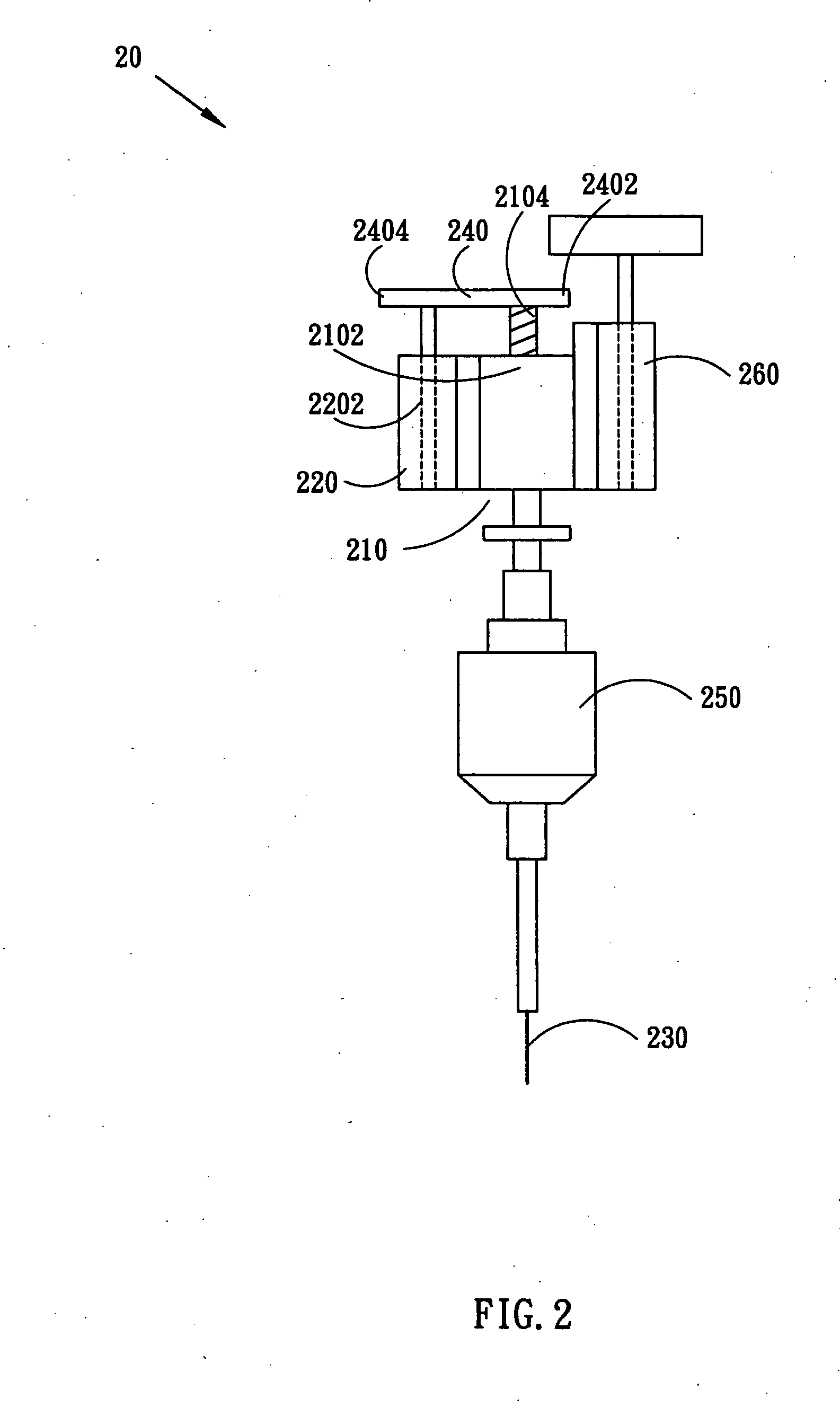
[0011]FIG. 2 is a plan view of the multi-axes inker 20 in the embodiment of the present invention. The multi-axes inker 20 comprises a driving device 210, an inker head 230, an anti-bias device 220 and an interconnecting shaft 240. The driving device 210 has a first axis 2102. The inker head 230 is used to mark the defective die. The anti-deflection device 220 has a second axis 2202. One end 2402 of the interconnecting shaft 240 is connected to the first axis 2102 and the other end 2404 of the interconnecting shaft 240 is connected to the second axis 2202. Therefor...


PUM


Abstract

An inker is usually used in electrical properties testing processes to mark the defective dies of the semiconductor wafer. However, the conventional inker having only one axis will be shaken during working time, resulting in making a mistake of marking the wrong dies. The present invention discloses a multi-axes inker to fix the problem. Another axis is added to the conventional inker. The new axis can help in restricting the original axis, so that the inker is stable and can mark the right dies without a mistake.

Description

FIELD OF THE INVENTION [0001] The present invention relates to an inker device, more particularly relates to a multi-axes inker device. DESCRIPTION OF THE PRIOR ART [0002] The fabrication of the semiconductor is included: IC design, wafer fabrication, wafer sort, IC packaging, and packaging test. In the wafer sort step, an inker is used to mark the defective die of the wafer after the defective die was distinguished from the operable dies. The present invention is about the improvement of the inker device and the probability of marking the wrong die can be reduced when the wafer die is too small. [0003]FIG. 1 is a plan view of the multi-axes inker 10 in the prior art. The inker 10 comprises a driving device 110, an inker head 120, and an interconnecting shaft 130. The driving device 110 has an axis 1102. The inker head 120 is used to mark the defective die. Moreover, the driving device 110 further has a spiral 1104 and a magnetic circuit (not shown). The spiral 1104 is disposed in t...

Claims


Application Information

Patent Timeline
Patent Type & Authority Applications(United States)
IPC IPC(8): B41F17/36B41F17/00
CPCH01L21/67282
Inventor DAI, JOHNNY
Owner KING YUAN ELECTRONICS
Why Eureka
Try Eureka