
Conductive keratoplasty probe guide device and methods thereof

a keratoplasty and probe guide technology, applied in the field of conductive keratoplasty, can solve the problems of increasing astigmatism, variability and over correction, and steeping of the central cornea, and solve the problem of optimizing the probe angle or depth for rf application

Inactive Publication Date: 2007-04-05
NANDURI PADMA +1
View PDF10 Cites 18 Cited by
  • Summary
  • Abstract
  • Description
  • Claims
  • Application Information

AI Technical Summary

Benefits of technology

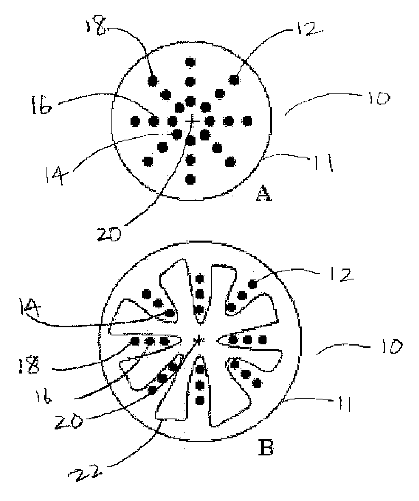
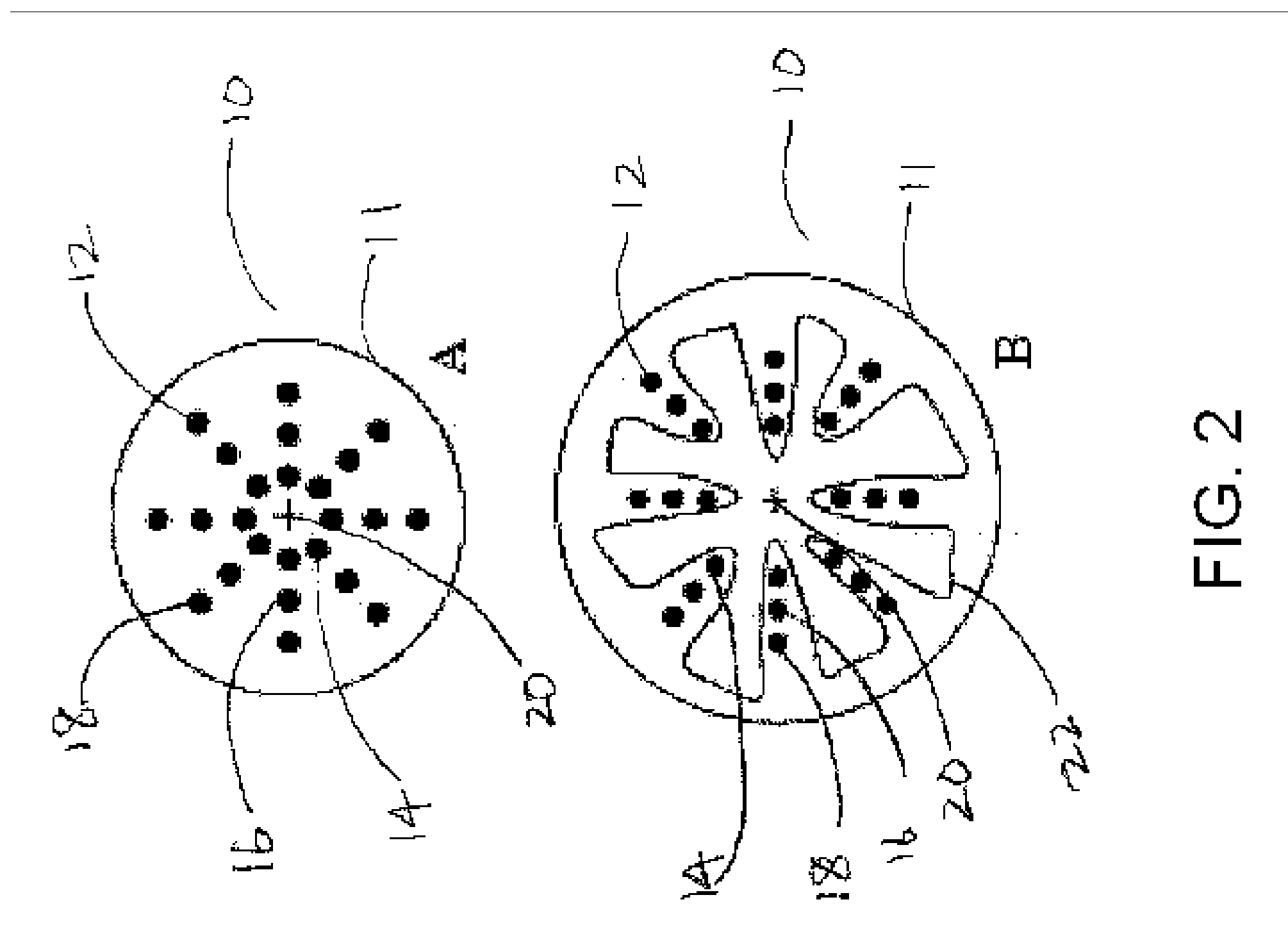
[0006] The present invention generally provides a biocompatible ophthalmic probe guide device having an arcuate member and at least one orifice disposed to admit and align a tip of an ophthalmic probe. In several preferred embodiments, the ophthalmic probe guide device is a conductive keratoplasty probe guide device having an arcuate member and at least one orifice capable of allowing a conductive keratoplasty probe to be inserted through the orifice. Also, the present invention teaches methods related to guiding a CK probe through this probe guide device. In other embodiments, the probe guide device is useful for guiding an ophthalmic surgical instrument for any corneal or limbal incision or an ophthalmic probe for procedures such as cataract surgery, astigmatic keratotomy, radial keratotomy, thermal keratoplasty, lamellar keratoplasty, scleral ports, or sclerectomy In such probe guide devices the arcuate member is configured to contact the region of cornea or sclera to be penetrated and the orifice is configured to admit and align the corresponding ophthalmic probe or instrument.

Problems solved by technology

The peripheral application of this treatment in a predetermined pattern creates a band of tightening and results in steepening of the central cornea.
In order to improve the accuracy and standardization of a CK probe, an inked marker is used, however during the treatment these ink marks may be obliterated resulting in variability and over corrections and increased astigmatism.
While this can aid the appropriate and efficient placement of the CK probe, it does not solve the problem of optimizing probe angle or depth for RF application.
This alteration has unintended consequences of inducing astigmatism, producing ghosting of vision or doubling of images and a unpredictable refractive outcome.

Method used


Image

  • Conductive keratoplasty probe guide device and methods thereof
  • Conductive keratoplasty probe guide device and methods thereof
  • Conductive keratoplasty probe guide device and methods thereof

Examples


Embodiment Construction

[0034] A: General

[0035] Before the present methods are described, it is understood that this invention is not limited to the particular methodologies, protocols, techniques, and preferred embodiments of the invention as described, as these may vary. It is also to be understood that the terminology used herein is for the purpose of describing particular embodiments only, and is not intended to limit the scope of the present invention which will be limited only by the appended claims.

[0036] It must be noted that as used herein and in the appended claims, the singular forms “a”, “an”, and “the” include plural reference unless the context clearly dictates otherwise. Thus, for example, reference to “an orifice” includes a plurality of such orifices and equivalents thereof known to those skilled in the art, and so forth. As well, the terms “a” (or “an”), “one or more” and “at least one” can be used interchangeably herein. It is also to be noted that the terms “comprising”, “including”, ...


PUM


Abstract

The present invention provides a biocompatible Conductive Keratoplasty probe guide device having an arcuate member and at least one orifice capable of allowing the probe to be inserted through the orifice. Also, the present invention teaches methods related to guiding a CK probe through this probe guide device.

Description

FIELD OF INVENTION [0001] The present invention generally relates to Conductive Keratoplasty, and specifically to probe guide devices and methods useful in improving the results of the Conductive Keratoplasty. BACKGROUND [0002] Conductive Keratoplasty®, or CK (Conductive Keratoplasty, CK and Keratoplast are registered trademarks of Refractec, Inc, Irvine, Calif.), is a thermal keratoplasty technology that uses low energy radio frequency (RF) current to shrink collagen, and is included in the term “RF thermal keratoplasty (RFTK)”. The low energy radiofrequency (RF) electric current is delivered directly into the corneal stroma through a hand piece and Keratoplast™ Tip, to produce refractive changes in the cornea. As a result of conducting a controlled amount of RF energy into the corneal stroma, the desired collagen shrinkage temperature is achieved. The peripheral application of this treatment in a predetermined pattern creates a band of tightening and results in steepening of the c...

Claims


Application Information

Patent Timeline
Patent Type & Authority Applications(United States)
IPC IPC(8): A61B19/00A61B18/18
CPCA61B19/20A61B2018/00291A61F9/0079A61F9/013A61B90/10
Inventor NANDURI, PADMADYER, T. AARON
Owner NANDURI PADMA
Learn More