Light-emitting device and method for manufacturing the same

Inactive Publication Date: 2007-04-05
SEMICON ENERGY LAB CO LTD
View PDF33 Cites 21 Cited by
  • Summary
  • Abstract
  • Description
  • Claims
  • Application Information

AI Technical Summary

Benefits of technology

[0029] According to the present invention, a gate electrode and a wiring is formed by a droplet discharging method, and Ag or Cu can be used for the conductive material. Also, an alloy containing Ag or Cu or a lamination of Ag and Cu can be also used. A silicon nitride film or a silicon oxynitride film is formed to be contact with a top surface of the gate electrode or the wiring, thereby preventing deterioration due to oxidation. Au, W, or Al may be used as the conductive material.
[0030] In the invention, the semiconductor film, which is a main portion of a TFT, can be also formed from a semi-amorphous semiconductor containing hydrogen and halogen, and having a crystal structure. Accordingly, a driver circuit only including an n-channel type thin film transistor can be provided. In other words, it is possible to form a driver circuit over one substrate by using a TFT in which a semiconductor containing hydrogen and halogen, and having a crystal structure is used as a semiconductor film and which can operate with an electric field effect mobility of 1 to 15 cm2/V-sec cm2.
[0031] According to one aspect of the invention, patterning of a wiring or a mask can be carried out directly by a droplet

Problems solved by technology

However, it is difficult to manufacture a display panel with good productivity and a low cost by a conventional patterning method.
Moreover, there is a problem that a material cost is wasted and disposa

Method used


Image

  • Light-emitting device and method for manufacturing the same
  • Light-emitting device and method for manufacturing the same
  • Light-emitting device and method for manufacturing the same

Examples


embodiment mode 1

[0073] A method for manufacturing a channel protective type TFT is explained in Embodiment mode 1.

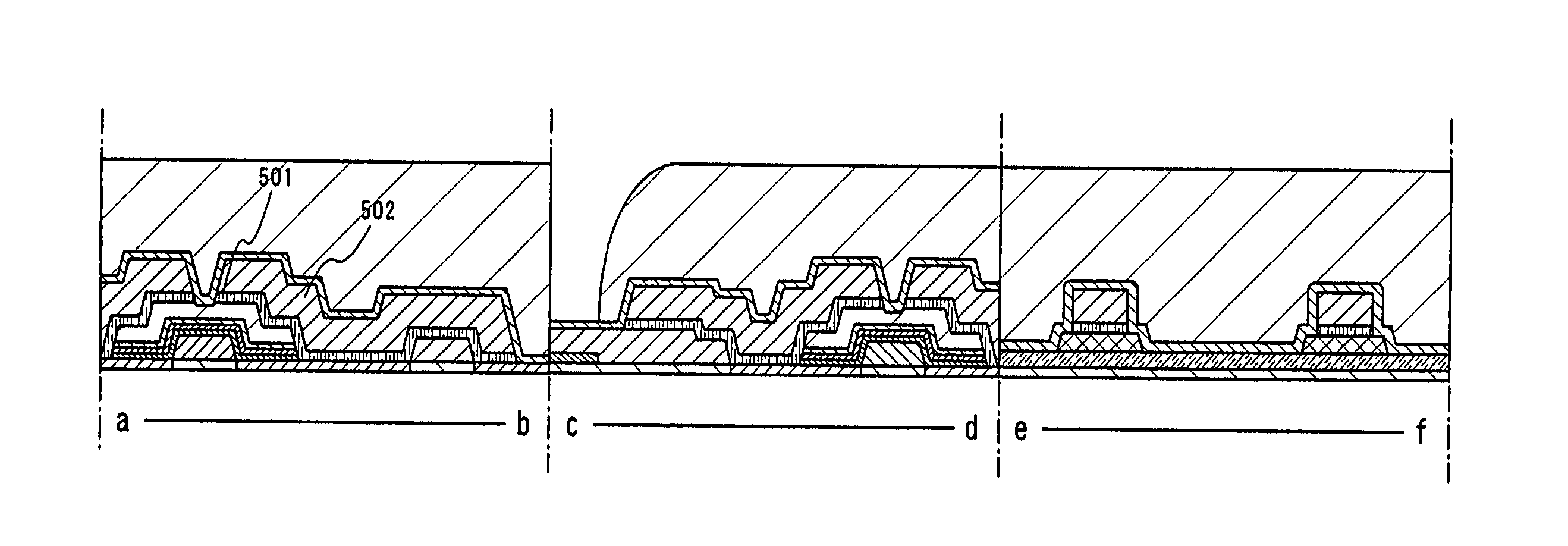
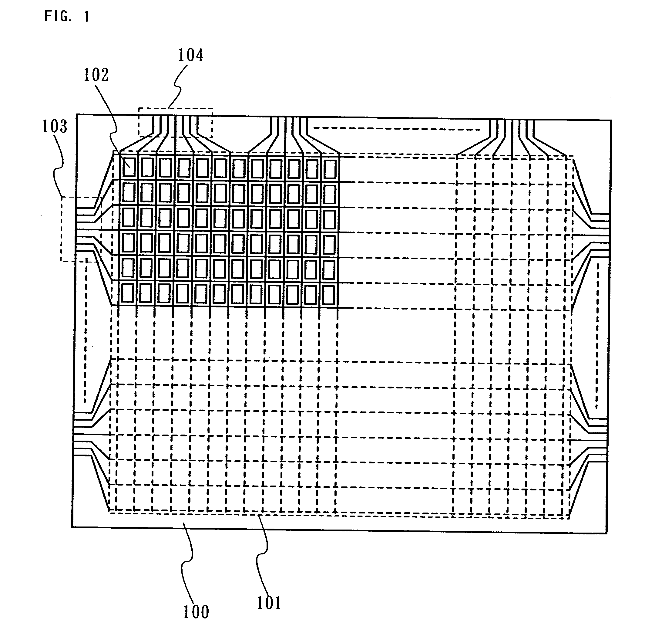
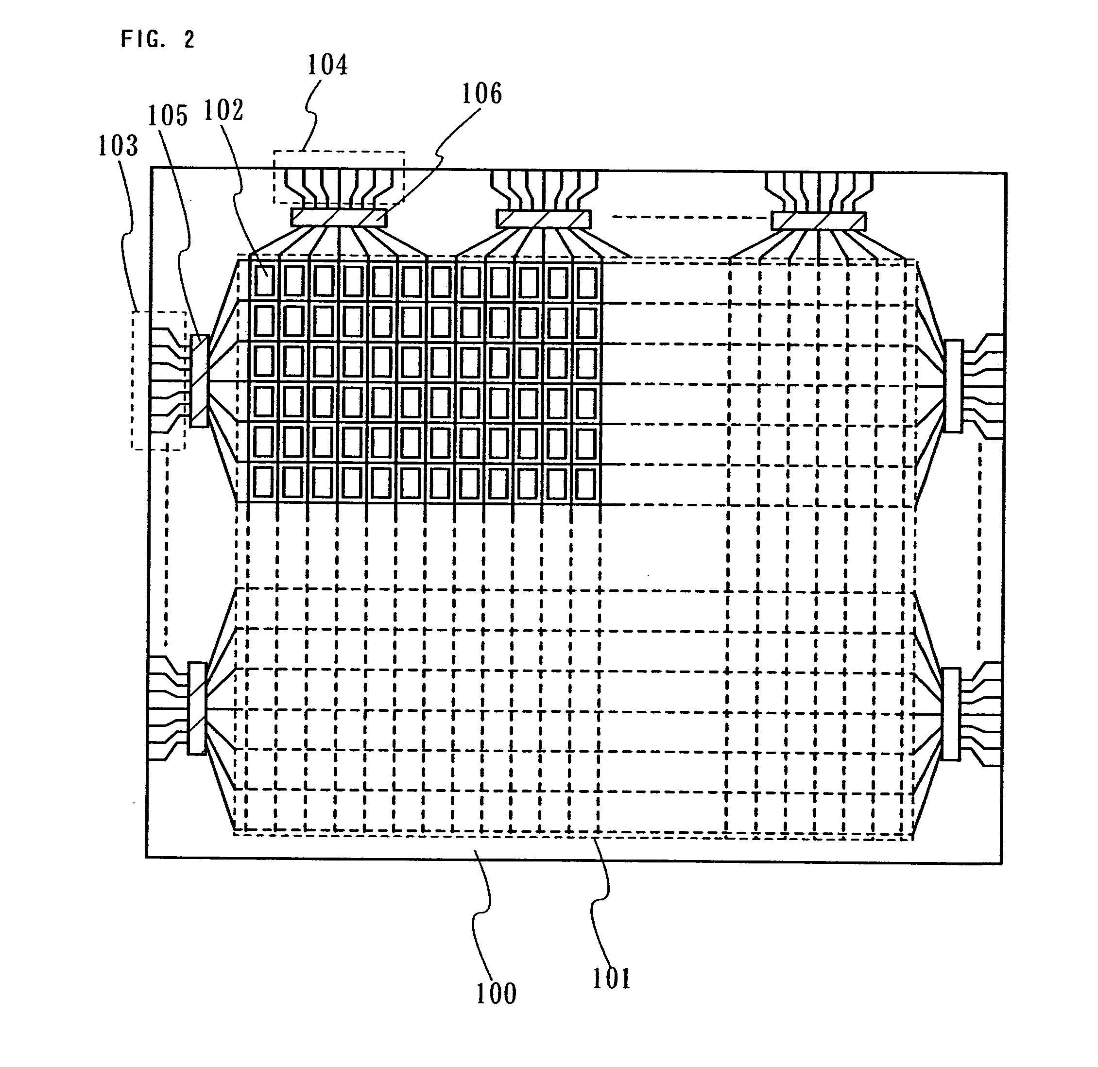
[0074]FIG. 4A shows a step of forming a gate electrode, and a gate wiring connected to the gate electrode over a substrate 100 by a droplet discharging method. Note that FIG. 4A shows a longitudinal sectional structure schematically, and FIG. 8 shows a planar structure corresponding to a-b, c-d and e-f thereof, and thus, the figures can be referred to at the same time.

[0075] A plastic substrate having the heat resistance that can withstand processing temperature of the manufacturing step, or other substrates can be used for the substrate 100, in addition to a non-alkaline glass substrate such as barium borosilicate glass, alumino borosilicate glass, or aluminosilicate glass manufactured with a fusion method or a floating method, and a ceramic substrate. A semiconductor substrate such as single crystal silicon, a substrate in which a surface of a metal substrate such as stainless is pr...

embodiment mode 2

[0105] A method for manufacturing a channel etch type TFT is explained in Embodiment mode 2.

[0106] A base film 201 is formed on a substrate 100, and a gate wiring 202, gate electrodes 203 and 204 are formed over the base film 201 by discharging a composition including a conductive material. After the gate wiring 202, the gate electrodes 203 and 204 are formed, the exposed base film 201 in the surface is treated and insulated to form an insulating layer 205 or removed by etching using the gate wiring 202, the gate electrodes 203 and 204 as a mask. Then, a gate insulating layer 206 is formed by plasma CVD or sputtering to have a single layer structure or a laminated layer structure. More preferably, a lamination of three layers, an insulating layer 207 of silicon nitride, an insulating layer 208 of silicon oxide and an insulating layer 209 of silicon nitride serves as the gate insulating layer. Further, a semiconductor film 210 serving as an active layer is formed. A mask 211 is form...

embodiment mode 3

[0109] A method for manufacturing a channel protective type TFT in which a first electrode is formed over a base film is explained in Embodiment mode 3.

[0110]FIG. 9A shows a step of forming a first electrode over a substrate 100, and FIG. 9B shows a step of forming a gate electrode, and a gate wiring connected to the gate electrode by a droplet discharging method. Note that FIG. 9A shows schematically a longitudinal sectional structure, and FIG. 13 shows a planar structure corresponding to a-b, c-d and e-f thereof, and thus, the figures can be referred to at the same time.

[0111] A plastic substrate having the heat resistance that can withstand processing temperature of the manufacturing step or the like can be used for the substrate 100, in addition to a non-alkaline glass substrate such as barium borosilicate glass, alumino borosilicate glass, or aluminosilicate glass manufactured by a fusion method or a floating method, and a ceramic substrate. In addition, a semiconductor subst...


PUM


Abstract

The present invention provides a display device and a manufacturing method thereof that can simplify manufacturing steps and enhance efficiency in the use of materials, and further, a manufacturing method that can enhance adhesiveness of a pattern. One feature of the invention is that at least one or more patterns needed for manufacturing a display panel, such as a conductive layer forming a wiring or an electrode or a mask for forming a desired pattern is/are formed by a method capable of selectively forming a pattern, thereby manufacturing a display panel.

Description

TECHNICAL FIELD [0001] The present invention relates to a light-emitting device including an active element such as a transistor formed over a large-size glass substrate and to a method for manufacturing the same. BACKGROUND ART [0002] Conventionally, a display panel of a so-called active matrix driving system constituted by a thin film transistor (hereinafter also referred to as a “TFT”) over a glass substrate is known. This active matrix display panel is manufactured by patterning various thin films by a light-exposure step using a photomask, similarly to a manufacturing technique of a semiconductor integrated circuit. [0003] Until now, there is employed a manufacturing method for cutting out plural display panels from one mother glass substrate and mass-producing efficiently. The size of a mother glass substrate used for manufacturing display panels is increased from 300 mm×400 mm of the first generation in the early 1990s to 680 mm×880 mm or 730 mm×920 mm of the fourth generatio...

Claims


Application Information

Patent Timeline
IPC IPC(8): H01L33/00H01L21/336H01L21/77H01L21/84H01L27/12H01L29/423H01L29/786
CPCH01L27/12H01L29/42384H01L29/66765H01L27/1292H01L27/156H01L27/1285H01L29/78696H01L27/1214H01L27/124H10K71/611H10K59/1213H10K59/1315H10K71/00H10K59/1201H01L27/1222H01L27/1251H01L29/78669
Inventor NAKAMURA, OSAMUFUJII, GENTATEISHI, FUMINORI
Owner SEMICON ENERGY LAB CO LTD
Why Eureka
Try Eureka