Image taking apparatus and program for multiple-exposure shooting

a technology for image taking apparatus and program, which is applied in the direction of exposure control, television systems, instruments, etc., can solve the problems of reducing the composite affecting the image quality of the composite image, and the user of the image taking apparatus does not always have a tripod, so as to prevent the degradation of the composite image quality and restrict the composite number

Inactive Publication Date: 2007-04-05
SANYO ELECTRIC CO LTD
View PDF7 Cites 20 Cited by
  • Summary
  • Abstract
  • Description
  • Claims
  • Application Information

AI Technical Summary

Benefits of technology

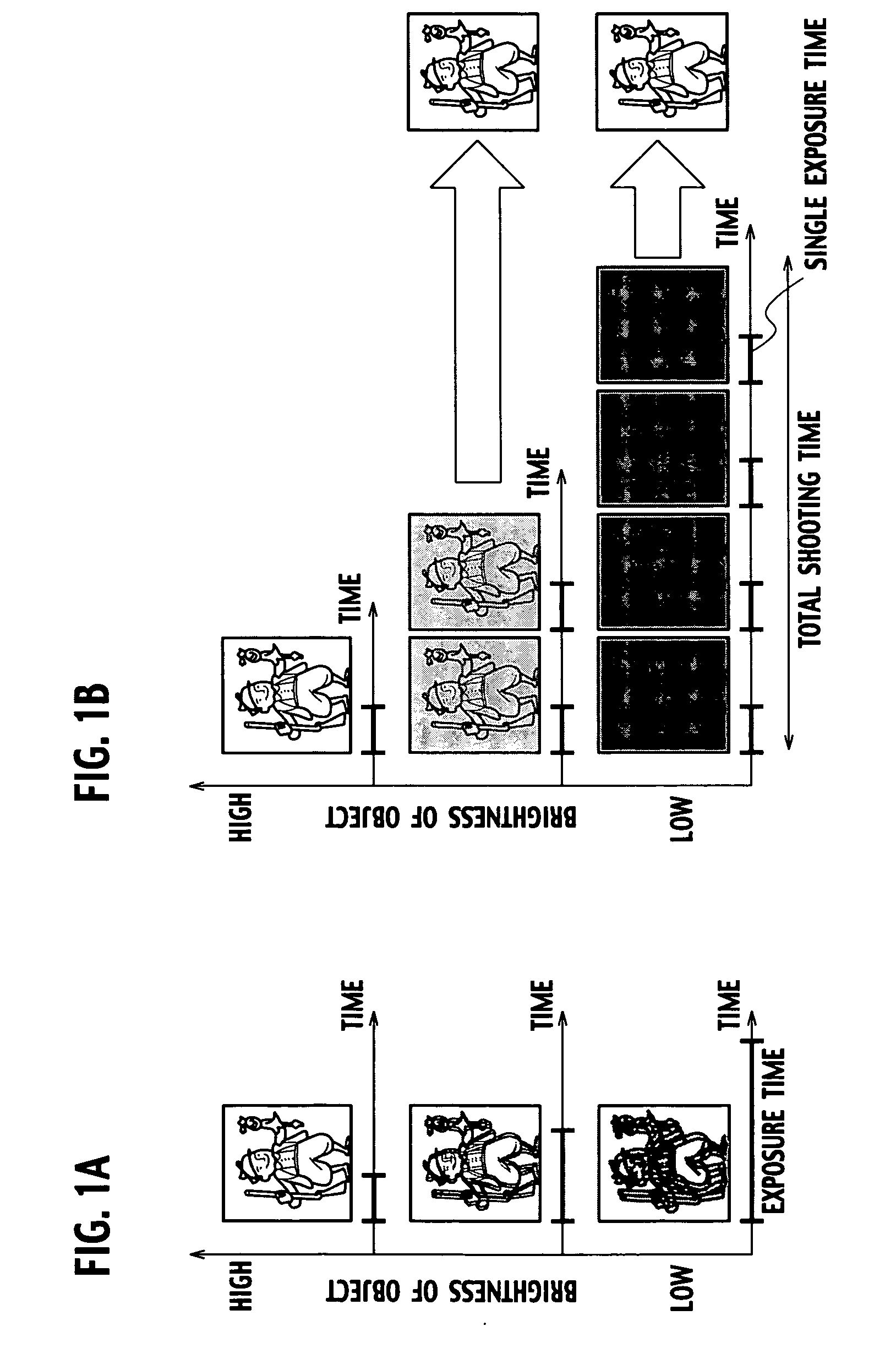
[0027] According to this feature, it is possible to restrict the composite number by calculating the upper limit value of the composite number. It is, therefore, possible to prevent degradation of image quality of the composite image attributable to an increase in the composite number.
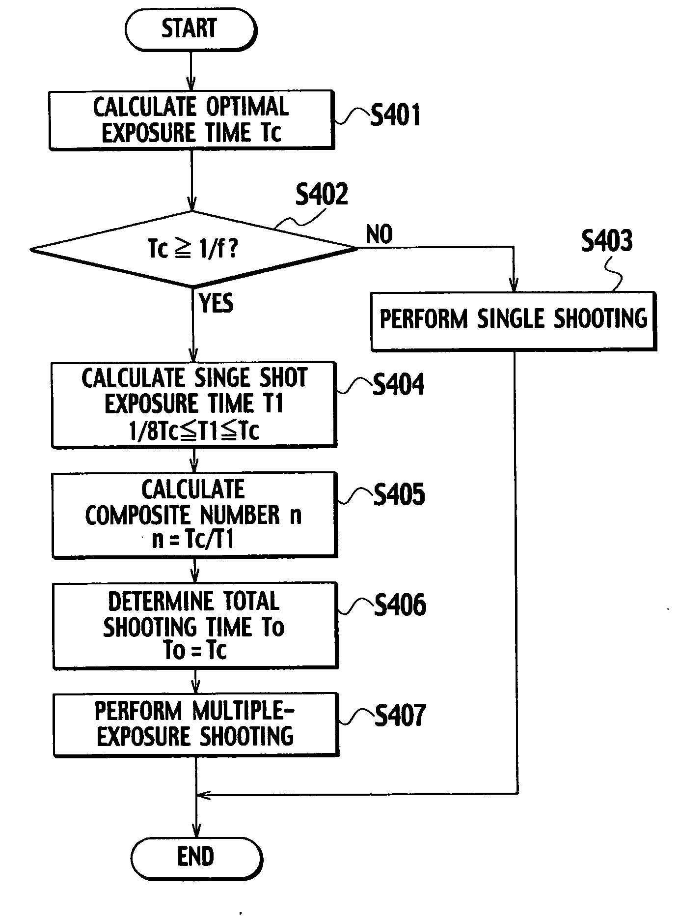
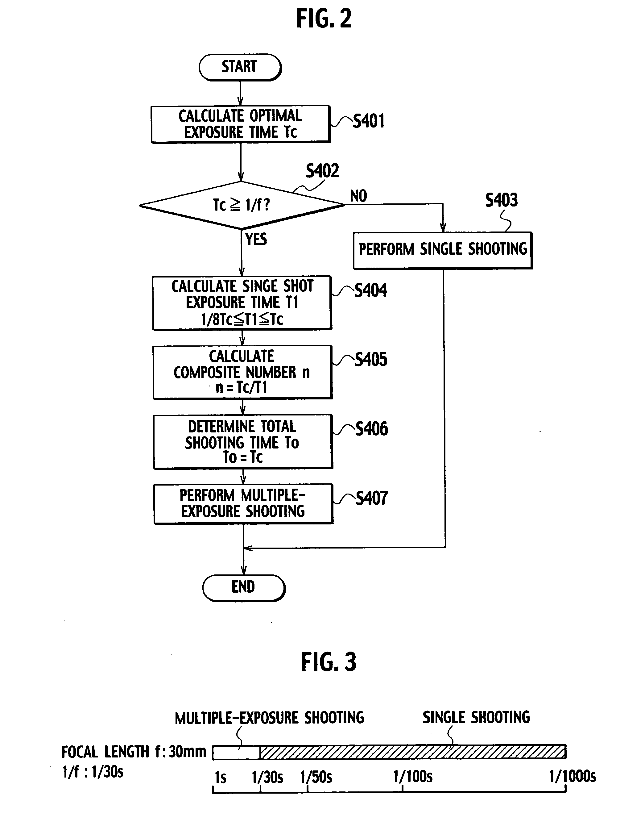
[0030] According to this feature, even in the case where the single shot exposure time is shorter than the frame period in the multiple-exposure shooting, the single shot exposure time is calculated to be not too long so as to suppress the total shooting time. In this way, it is possible to prevent a camera shake attributable to the long single shot exposure time.
[0032] According to this feature, it is possible to suppress the total shooting time in the multiple-exposure shooting even in the case where the single shot exposure time is shorter than the frame period. In this way, it is possible to prevent a camera shake attributable to the long total shooting time.

Problems solved by technology

A user of an image taking apparatus, however, does not always have a tripod.
Meanwhile, battery power would soon run out when using a flash lamp frequently and the flash lamp would not be effective for shooting a distant object.
Thus, in the case where the optimal exposure time Tc is shorter than 1 / f second, the conventional image taking apparatus cannot perform the multiple-exposure shooting even in a case where a user of the conventional image taking apparatus is highly likely to cause a camera shake at the optimal exposure time Tc.
Accordingly, the conventional image taking apparatus cannot prevent a camera shake in this case.
Accordingly, there has been a problem where a camera shake cannot be prevented in this case.

Method used


Image

  • Image taking apparatus and program for multiple-exposure shooting
  • Image taking apparatus and program for multiple-exposure shooting
  • Image taking apparatus and program for multiple-exposure shooting

Examples


Embodiment Construction

Configuration of an Image Taking Apparatus of the Embodiments

[0045] A configuration of an image taking apparatus according to embodiments will be described with reference to FIG. 4 to FIG. 6C. As show in FIG. 4, an image taking apparatus 100 includes a lens 110, an diaphragm 120, image sensor 130, a shooting controller 140, an image processor 150, and a motion detecting and combining unit 160, and is therefore configured to perform multiple-exposure shooting and single shooting. Here, an object image may be any one of a photoelectrically converted image and a shot image.

[0046] The photoelectrically converted image is generated by the image sensor 130 exposed through the lens 110 and the diaphragm 120 by means of performing photoelectric conversion, accumulating electric charges, and reading the accumulated electric charges.

[0047] Meanwhile, the shot image is obtained by subjecting the photoelectrically converted image to a predetermined process. The predetermined process includes...


PUM


Abstract

The exposure time calculator calculates exposure time of image sensor based on an aperture value corresponding to a diaphragm and brightness of an object. The predetermined time calculator calculates predetermined time based on a focal length of a lens and a predetermined coefficient. The shooting mode determining unit determines execution of multiple-exposure shooting to obtain a composite image of the object by obtaining multiple object images and then combining the multiple object images in a case where the exposure time is equal to or longer than the predetermined time. The motion detector detects motion among the multiple object images in the multiple-exposure shooting. The predetermined coefficient calculator updates a predetermined coefficient based on the detected amount of motion.

Description

CROSS REFERENCE TO RELATED APPLICATIONS [0001] This application is based upon and claims the benefit of priority from Japanese Patent Application No. 2005-287820 filed on Sep. 30, 2005, the entire contents of which are incorporated herein by reference. BACKGROUND OF THE INVENTION [0002] 1. Field of the Invention [0003] The present invention relates to an image taking apparatus and a program for obtaining an object image and to perform multiple-exposure shooting by use of the object image. [0004] 2. Description of Related Art [0005] In a conventional image taking apparatus such as a digital still camera, there has been known a technique to increase a shutter speed to prevent a camera shake at the time of image shooting, or in other words, to shorten exposure time of image sensor. To be specific, to prevent a camera shake at the time of image shooting, it is preferable to set the exposure time equal to or below 1 / f second in a case where a focal length of a lens is set to f mm. [0006]...

Claims


Application Information

Patent Timeline
Patent Type & Authority Applications(United States)
IPC IPC(8): G03B7/10
CPCH04N5/23248H04N5/23254H04N5/2327H04N5/235H04N5/243H04N23/68H04N23/6811H04N23/684H04N23/70H04N23/76
Inventor TOMINAGA, RYUICHIROMORI, YUKIOOKADA, SEIJIHAMAMOTO, YASUHACHIYOKOHATA, MASAHIRO
Owner SANYO ELECTRIC CO LTD
Why Eureka
Try Eureka