Interface protocol method and system

a protocol and interface technology, applied in the field of interface protocols, can solve the problems of overpowering the processing power available on the printer cartridge, requiring a large amount of processing power,

Inactive Publication Date: 2007-04-05
LEXMARK INT INC
View PDF5 Cites 69 Cited by
  • Summary
  • Abstract
  • Description
  • Claims
  • Application Information

AI Technical Summary

Problems solved by technology

Unfortunately, a considerable amount of processing power may be required to generate the digital signature, which may overwhelm the processing power available on the printer cartridge.

Method used


Image

  • Interface protocol method and system
  • Interface protocol method and system
  • Interface protocol method and system

Examples


Embodiment Construction

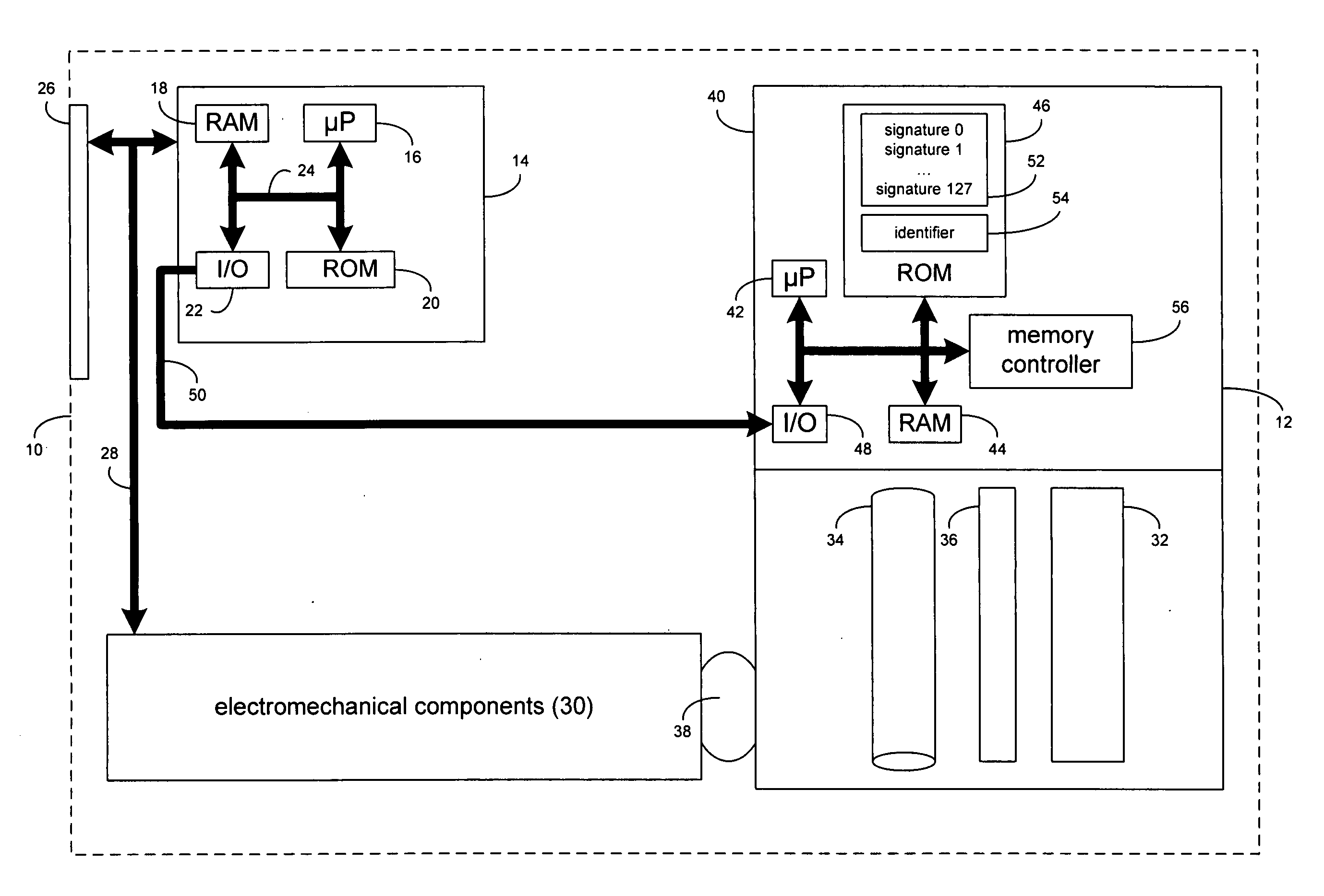
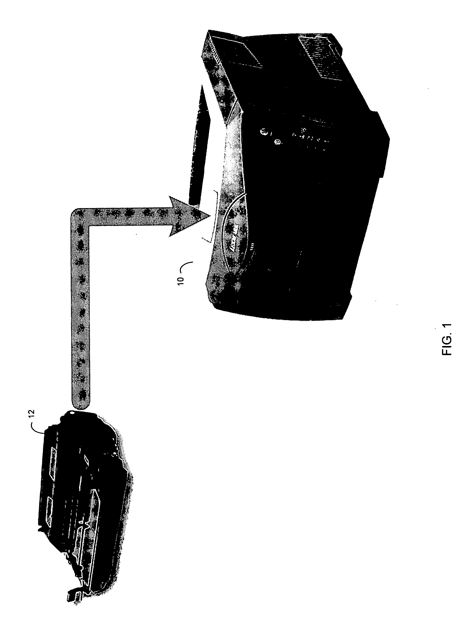
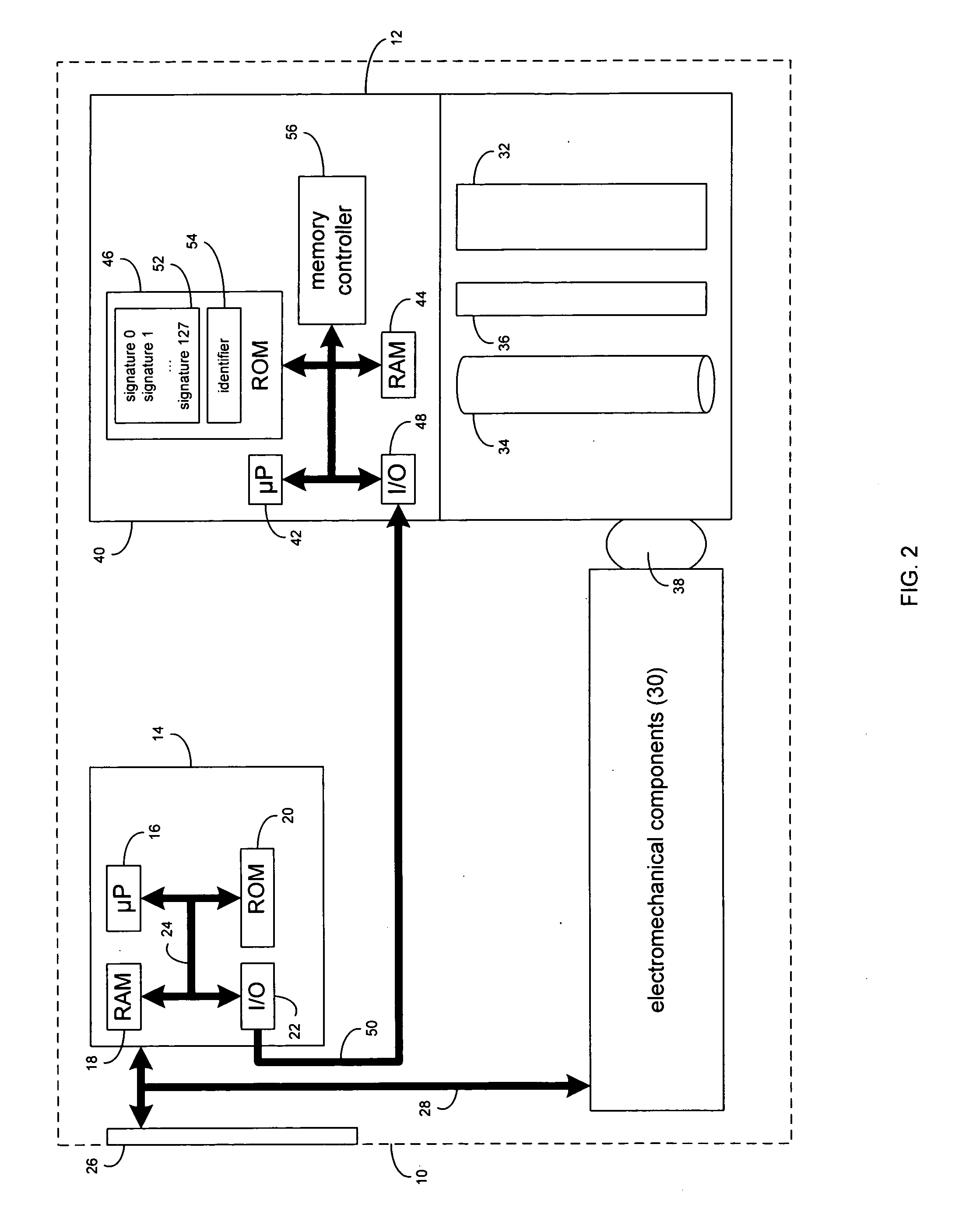
[0019] Referring to FIG. 1, there is shown a printing device 10 and a printer cartridge 12 for use within printing device 10. Printing device 10 is typically coupled to a computing device (not shown) via e.g. a parallel printer cable (not shown), a universal serial bus cable (not shown), and / or a network cable (not shown).

[0020] As is known in the art, printing device 10 is a device that accepts text and graphic information from a computing device and transfers the information to various forms of media (e.g., paper, cardstock, transparency sheets, etc.). Further and as is known in the art, a printer cartridge 12 is a component of printing device 10, which typically includes the consumables / wear components (e.g. toner, a drum assembly, and a fuser assembly, for example) of printing device 10. Printer cartridge 12 typically also includes circuitry and electronics (not shown) required to e.g., charge the drum and control the operation of printer cartridge 12.

[0021] Referring also to ...


PUM


Abstract

A claimant device includes a memory device for storing a unique claimant device identifier and a plurality of unique digital signatures. Each digital signature is based, at least in part, upon the unique claimant device identifier.

Description

TECHNICAL FIELD [0001] This disclosure relates to an interface protocol and, more particularly, to an interface protocol for use in a printing device. BACKGROUND [0002] Printing devices often use an electronic authentication procedure to determine if the printer cartridge installed in the printing device is an authentic printer cartridge (i.e., a printer cartridge that is allowed to be used within the printing device). Additionally, the electronic authentication procedure may determine what licensing privileges the cartridge is allowed. [0003] The principal technique used in the electronic authentication procedure involves a “challenge” protocol in which a data set is provided to two “authentication engines”, the first being in the printer cartridge and the second being in the printing device. During authentication, both the printer cartridge and the printing device “seed” the data set with a “secret value” that is not revealed by the printer cartridge or the printing device. Typica...

Claims


Application Information

Patent Timeline
Patent Type & Authority Applications(United States)
IPC IPC(8): H04L9/00
CPCG06F21/33G06F2221/2129H04L9/3247
Inventor ADKINS, CHRISTOPHER ALANBOOTH, JAMES RONALDSTRUNK, TIMOTHY LOWELL
Owner LEXMARK INT INC
Why Eureka
Try Eureka