
Hybrid hydraulic system and work machine using same

a hybrid hydraulic system and work machine technology, applied in the direction of hydraulic couplings, couplings, mechanical devices, etc., can solve the problems of consuming energy provided for hydraulic cylinder actuation in the hydraulic system, and affecting the operation of the hydraulic system. the effect of reducing the number of hydraulic cylinders

Inactive Publication Date: 2007-04-12
CATERPILLAR INC
View PDF9 Cites 41 Cited by
  • Summary
  • Abstract
  • Description
  • Claims
  • Application Information

AI Technical Summary

Problems solved by technology

Actuation of hydraulic cylinders in the hydraulic system consumes energy provided by the work machine engine, or another power source such as a fuel cell or battery.
Where hydraulic pressure is bled to a low pressure drain as the boom arm is lowered, the potential energy residing in the raised boom arm can be lost.
Even the most advanced hybrid hydraulic systems, however, are not without drawbacks.
In particular, because the rod occupies a certain fluid volume, when fluid is transitioned from the rod side to the head side or a drain, a void may form in the rod side of the actuator.
During operation, the generation of such a void may result in a delay in the motion of the hydraulic actuator until the system pumps and / or accumulator can provide the required fluid volume.
In certain systems, voiding in the hydraulic pump itself may result from unequal fluid volumes in the head and rod, for example, when extending a hydraulic actuator.
While the Rahmfeld and Ivantysynova design offers certain advantages, it also presents certain disadvantages, in particular the fact that much of the hydraulic energy from an overrunning load cannot be stored in the relatively low pressure accumulator.

Method used


Image

  • Hybrid hydraulic system and work machine using same
  • Hybrid hydraulic system and work machine using same
  • Hybrid hydraulic system and work machine using same

Examples


Embodiment Construction

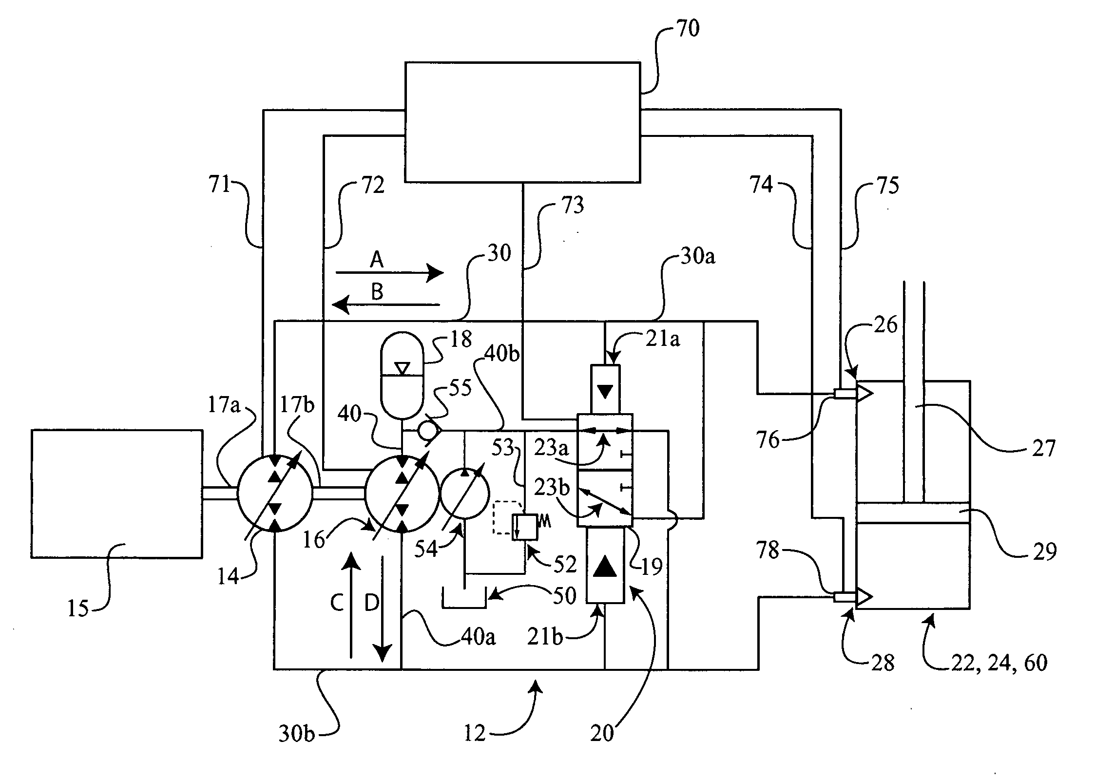
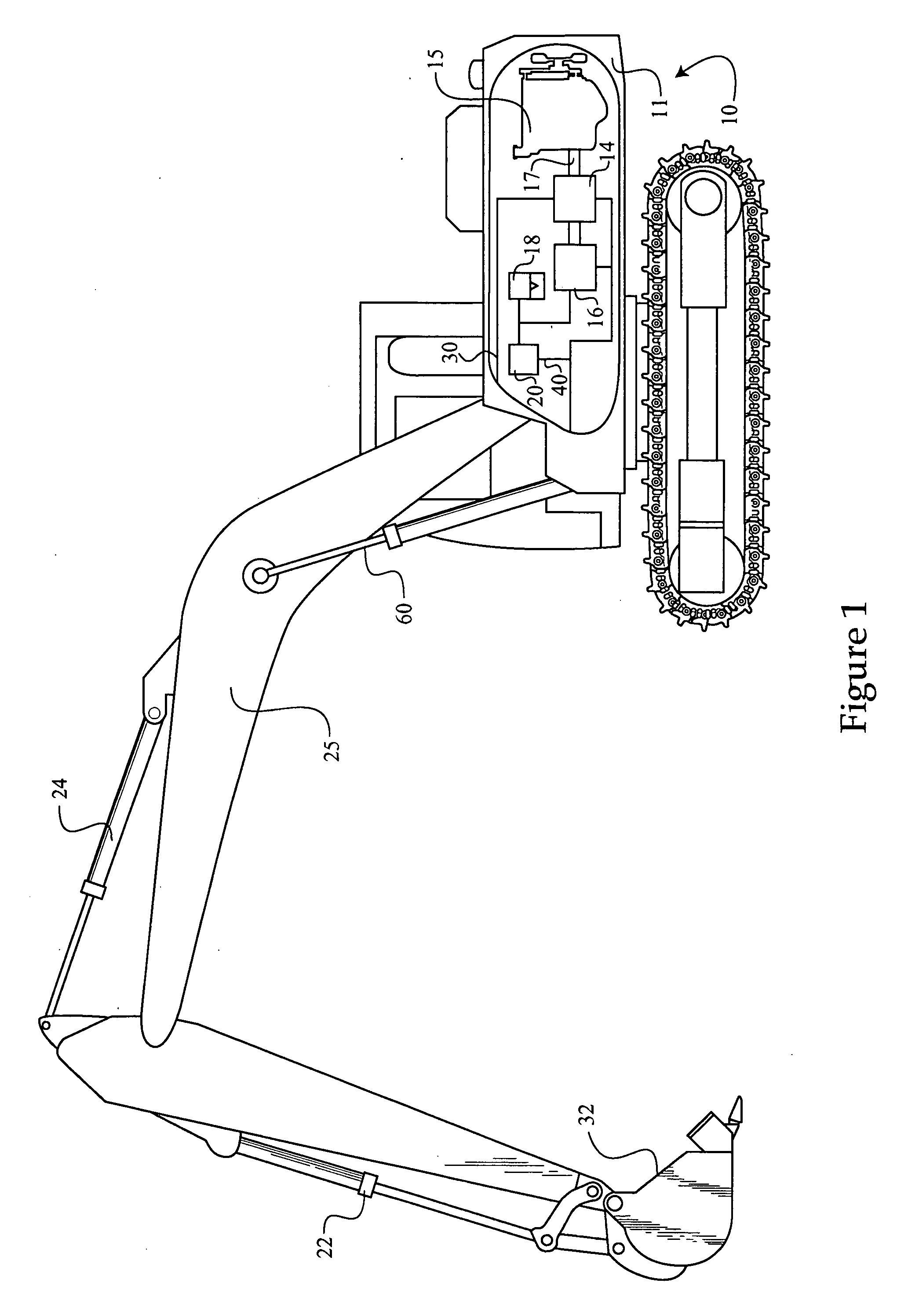
[0013] Referring to FIG. 1, there is shown a work machine 10 having a work machine body 11, a work implement arm 25 or boom arm and a hydraulic system 12. Hydraulic system 12 consists of a “hybrid” hydraulic system wherein hydraulic energy may be selectively stored and recovered, as described herein. Work machine 10 is illustrated in the context of a track-type excavator having a hydraulically actuated work implement such as a bucket 32. It should be appreciated, however, that work machine 10 is illustrative only, and the present disclosure will be applicable to virtually any hydraulic system having at least one hydraulic actuator, which may be a hydraulic cylinder.

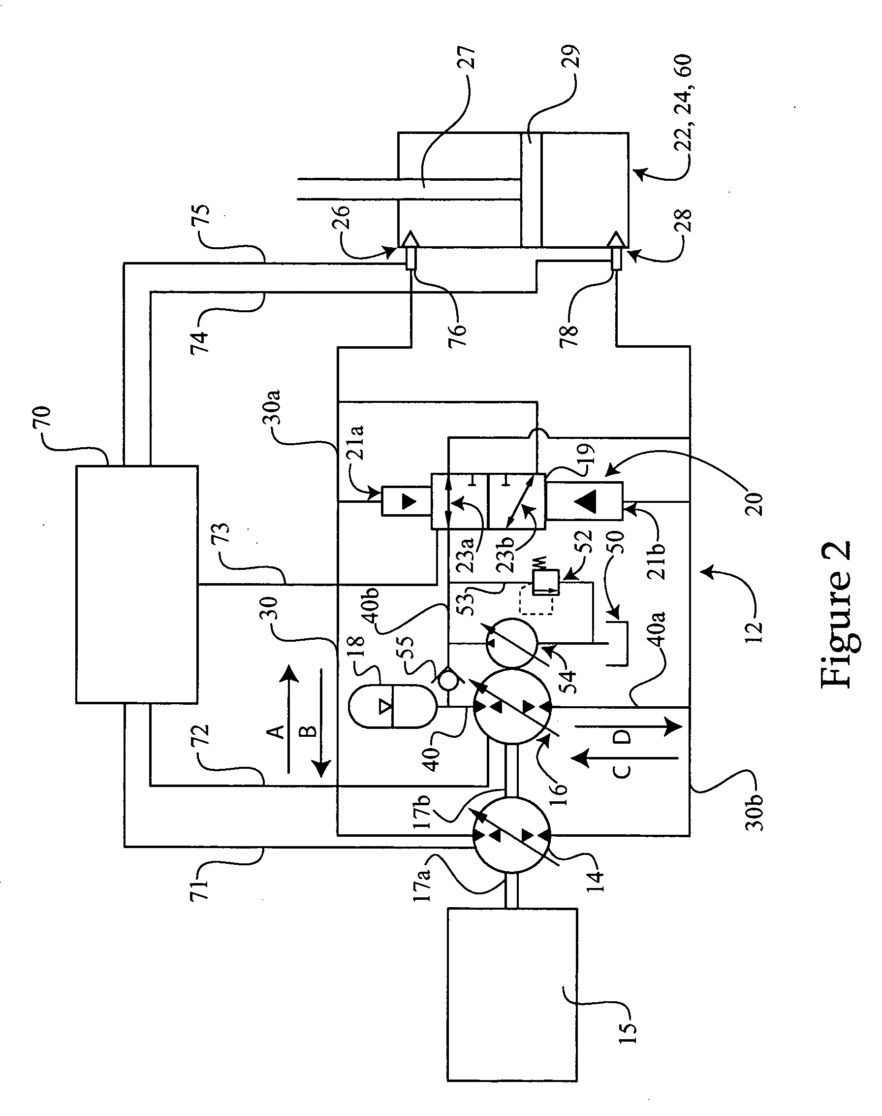
[0014] Work machine 10 may further include an engine 15, which may be a conventional internal combustion engine, coupled with an output shaft 17. Rotation of output shaft 17 may power a first hydraulic pump 14, and a second hydraulic pump 16. It is contemplated that both pumps 14 and 16 will be overcenter bi-directional ...


PUM


Abstract

A hydraulic system and work machine are provided, the hydraulic system including at least one hydraulic cylinder with a first port and a second port connected by a first fluid passage. A first pump, which is a bi-directional hydraulic pump is positioned within the first fluid passage, and a second pump is positioned in parallel with the first pump and disposed within a second fluid passage. An accumulator fluidly connects with the second fluid passage.

Description

TECHNICAL FIELD [0001] The present disclosure relates generally to hydraulic systems for work machines, and relates more particularly to a hybrid hydraulic system having first and second hydraulic pumps positioned in parallel in a hydraulic circuit, and an accumulator for storing and recovering hydraulic energy of the hydraulic system. BACKGROUND [0002] Hydraulic systems in a wide variety of forms are indispensable components of many modem work machines. Virtually all tractors, loaders, excavators and other off highway work machines utilize hydraulically actuated work implements. In a typical design, the work machine hydraulic system will include one or more hydraulic pumps coupled with an engine of the work machine and operable to supply a pressurized hydraulic fluid to hydraulic actuators for adjusting the position of a work implement, such as a bucket or blade. In other applications, hydraulic actuators may be used in work machine stabilizers, and even in steering systems of work...

Claims


Application Information

Patent Timeline
Patent Type & Authority Applications(United States)
IPC IPC(8): F16D31/02
CPCE02F9/2217E02F9/2292F15B7/006F15B21/08F15B21/14F15B2211/20546F15B2211/20569F15B2211/20576F15B2211/212F15B2211/63F15B2211/7053F15B2211/88
Inventor BRINKMAN, JASON L.GUPTA, PINAKI
Owner CATERPILLAR INC
Learn More