Electrochemical thermodynamo

a technology of electrochemical and thermodynamo, which is applied in the field of electrochemical cells, can solve the problems of low efficiency in the energy conversion from electric energy to chemical energy, high cost, and high purity of electrolytic produced hydrogen, and achieve the effect of improving the yield of an electrochemical cell

Inactive Publication Date: 2007-04-12
RICOTTI PAOLO +2
View PDF4 Cites 14 Cited by
  • Summary
  • Abstract
  • Description
  • Claims
  • Application Information

AI Technical Summary

Benefits of technology

[0017] Scope of the present invention is the improvement of the yield of an electrochemical cell with porous electrodes able to be used either as electrolyser or as fuel cell. Unexpectedly, its has been found that by applying a pressure modulation to the electrolyte the yield improves up to 30% using the conventional cell with porous carbon / nickel-mesh electrodes.

Problems solved by technology

The electrolytic produced hydrogen has an high purity, but an high cost due both to the high cost of electric energy and to the low yield, i.e. low efficiency in the energy conversion from electric energy to the chemical energy.
The incentives to improve the efficiency of the electrolytic production of hydrogen are presently small: although the added value of high purity of electrolytic hydrogen would render the higher cost unimportant, such applications are rare and the use of hydrogen for the production of energy is uneconomical either for production of electrolytic hydrogen with high yields.
In order to contribute to the development of systems which avoid the use of fossil fuels such as coal or natural gases, the choice of systems producing hydrogen from electrolysis of water is unavoidable.
The AFC needs pure gases in input which limited their application and the further development of this technology.
The alkaline fuel cells are easily polluted from the carbon dioxide contained in the hydrogen produced from the hydro-reforming of the fossil fuels.

Method used


Image

  • Electrochemical thermodynamo
  • Electrochemical thermodynamo
  • Electrochemical thermodynamo

Examples


Embodiment Construction

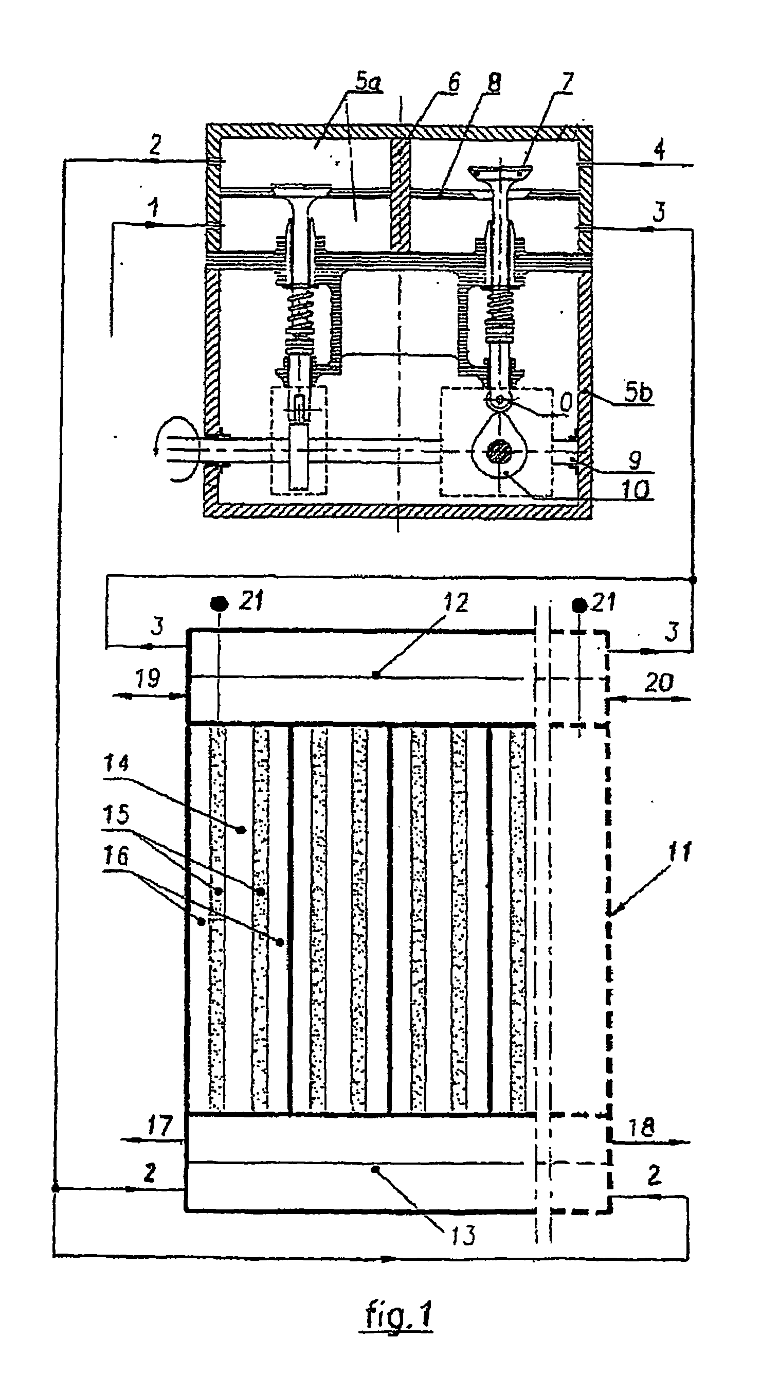
[0026] Preferred embodiments of the electrochemical module according to the present invention are described in detail below by referring to the accompanying drawings.

[0027] Alkaline fuel cells use an electrolyte that is an aqueous solution of potassium hydroxide (KOH) retained in porous electrodes. The concentration of KOH can be varied with the fuel cell operating temperature, which ranges from 65° C. to 220° C. The charge carrier for an AFC is the hydroxyl ion (OH—) that migrates from the cathode to the anode where they react with hydrogen to produce water and electrons. Water formed at the anode migrates back to the cathode to regenerate hydroxyl ions. The chemical reactions at the anode and cathode in an AFC are shown below. This set of reactions in the fuel cell produces electricity and by-product heat. [0028] Anode Reaction: 2H2+4OH−=>4H2O+4e−[0029] Cathode Reaction: O2+2H2O+4e−=>4OH−[0030] Overall Net Reaction: 2H2+O2=>2H2O

[0031] In the alkaline electrolysis cell, this set ...


PUM

PropertyMeasurementUnit
pressureaaaaaaaaaa
pressureaaaaaaaaaa
temperatureaaaaaaaaaa

Abstract

Electrochemical cells modules made up of couples of catalytic multilayer porous electrodes forming the anodes and the cathodes and delimitating external gaseous areas and internal areas containing the electrolyte wherein the pressure modulators, generating two pressure cycles independently synchronized but of opposite phase, act at the inlet and at the outlet of the electrolyte and the multilayer porous electrodes are weeping on the gas side. According to a preferred embodiment the multilayer porous electrodes are hydrophobic and conductive on the gas side, the conductive and catalytic middle layers are hydrophobic and hydrophilic, the non-conductive and non-catalytic layer on the electrolyte side is hydrophilic. Furthermore, the present invention provides the electrochemical process using the above described electrochemical cell according to which the gas is maintained at a pressure P up to 200 bar, the electrolyte pressure is varied stepwise between P+dP and P+dp by generating on the electrolyte positive pressure waves of amplitude dP and dp at the frequency f.

Description

FIELD OF THE INVENTION [0001] The present invention generally relates to the field of the electrochemical cell. More particularly, the present invention relates to an electrochemical cell for water electrolysis and / or for the production of electricity using traditional technologies: the improvement increases the energetic yields. BACKGROUND OF THE INVENTION [0002] The exhaustion of fossil fuel reserves together with the environmental and climatic changes linked to their utilization has developed new technologies which will utilize the hydrogen as source of energy. The advantages are easily foreseeable using as energy source the sun, the renewable solar energy will be utilize to decompose the water in hydrogen and oxygen, hydrogen bums either in conventional engines or in fuel cells without pollutants emission to generate electric energy. Many technological aspects have still to be solved in order to implement this project, in particular case those referring to the transformation of ...

Claims


Application Information

Patent Timeline
Patent Type & Authority Applications(United States)
IPC IPC(8): C25B1/02C25B1/12C25B15/00H01M4/86H01M8/04H01M8/18
CPCC25B1/12C25B15/00H01M4/8605H01M8/04007H01M8/083H01M8/186Y02E60/366Y02E60/528Y02E60/36Y02E60/50C25B1/04C25B9/05
Inventor MELOSI, MARIO
Owner RICOTTI PAOLO
Why Eureka
Try Eureka