

Foldable chair mat
Patent Information
- Authority / Receiving Office
- US · United States
- Current Assignee / Owner
- THE ROBBINS CO
- Publication Date
- 2007-04-12
- Estimated Expiration
- Not applicable · inactive patent
Smart Images
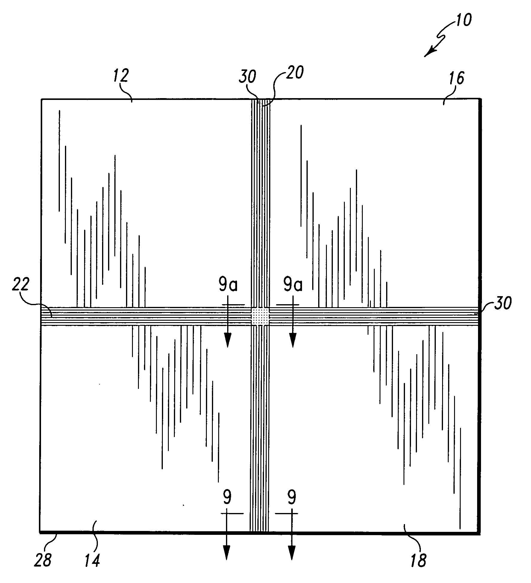
Figure 1 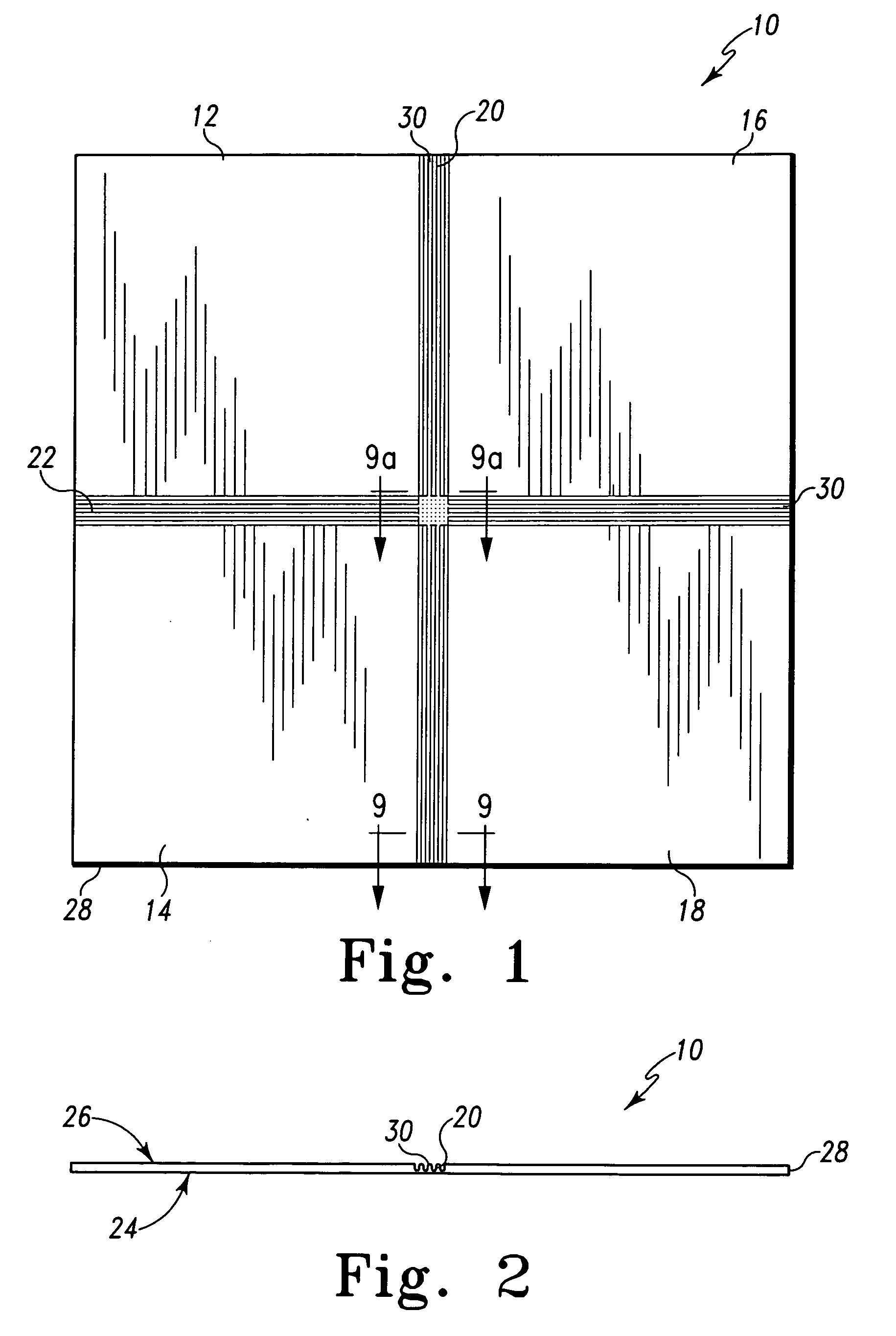
Figure 2 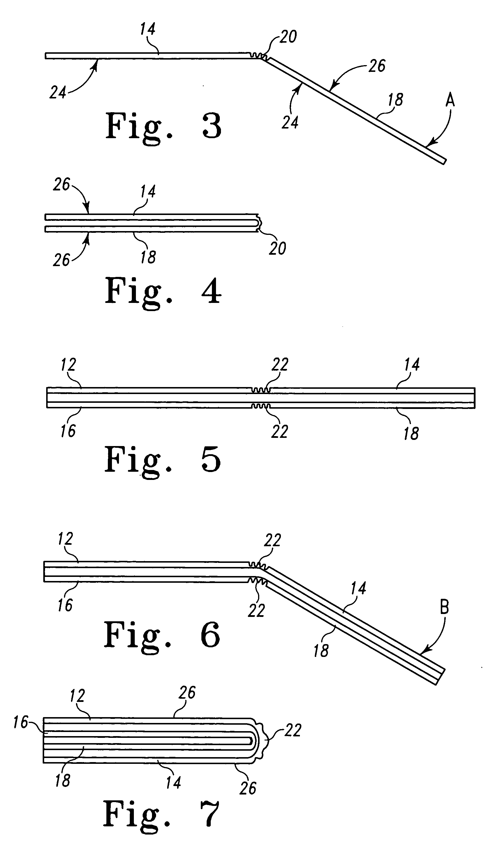
Figure 3
Abstract
Description
CROSS-REFERENCE TO RELATED APPLICATIONS
[0001] The present application is related to and claims all available benefit from U.S. Provisional Application Ser. No. 60 / 724,080 filed Oct. 6, 2005.BACKGROUND
[0002] The present invention is directed to chair mats and specifically, to chair mats typically used under chairs in order to protect an underlying carpet. In particular, the present invention relates to a chair mat having features that enhance the ease of transport and handling, and improve marketability.
[0003] Chair mats for office and home use are well known. Chair mats that are designed to be applied over carpeting typically are formed of a semi-rigid plastic. Often an underside surface of the chair mat has an array of short spikes or other protrusions that are intended to hold the mat firmly in place on the carpeting. While chair mats can be made without any spikes, the mats tend to move relative to the carpet in response to movement of any chair on the top surface of the mat. ...