Storage control system and method

a storage control and control system technology, applied in the field of backup and recovery, can solve the problems of inhibiting the performance degradation of access to the first logical volume, increasing the load on the host computer employed by the user, so as to achieve the effect of not increasing the load on the hos

Inactive Publication Date: 2007-04-12
HITACHI LTD
View PDF8 Cites 54 Cited by
  • Summary
  • Abstract
  • Description
  • Claims
  • Application Information

AI Technical Summary

Benefits of technology

[0021] With the present invention, data can be recovered at the point in time the consistency was provided, without increasing a load on the host.

Problems solved by technology

This results in an increased load on a host computer employed by the user.
Furthermore, if the frequency of snapshots is increased to realize them with CoW, the number of CoW cycles increases accordingly and the access performance is degraded (for example, a long time passes from the instant the write command is received to the instant the data writing is completed).
On the other hand, with the journaling technology, performance degradation of access to the first logical volume is inhibited by recording a journal log in the second logical volume, which is separated from the first logical volume where data are written following the write command from the host computer.
However, a journal log comprising a write command and data has to be kept each time the write command and data are received and a large storage capacity is required.
Furthermore, because data recovery requires that the data be sequentially recovered in an order inverted with respect to that of the write command processing, a long time is required for the recovery.
A method in which a user frequently provides a check point indication to a disk array device can be considered for shortening the recovery interval, but this apparently increases a load on the host computer, in the same manner as with the snapshot technology.
Furthermore, because the snapshots have to be taken frequently in order to reduce the regeneration quantity of data, the above-described problem of increased load on the host computer is not resolved.

Method used


Image

  • Storage control system and method
  • Storage control system and method
  • Storage control system and method

Examples


Embodiment Construction

[0036] An embodiment of the present invention will be described below in greater detail with reference to the appended drawings.

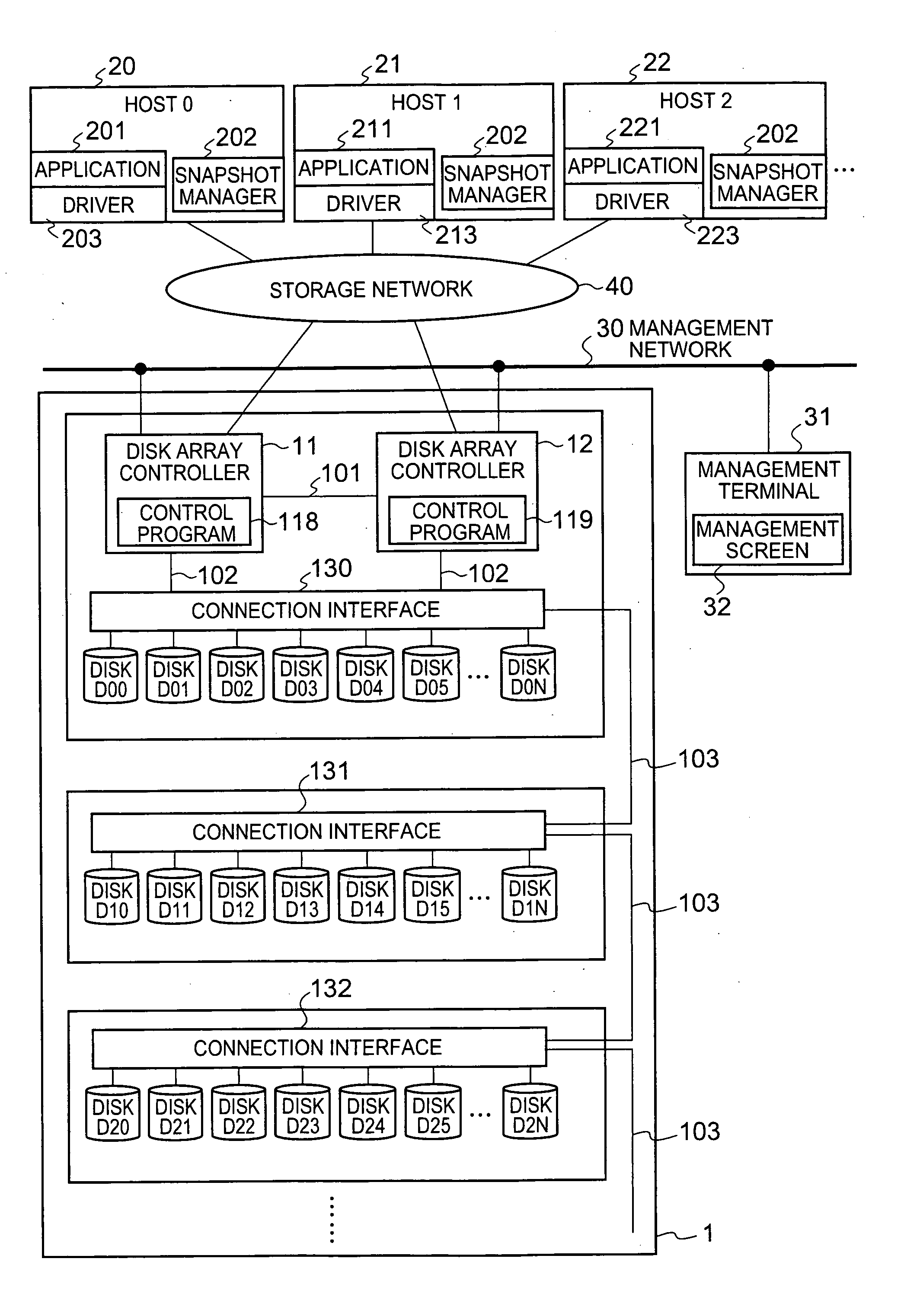
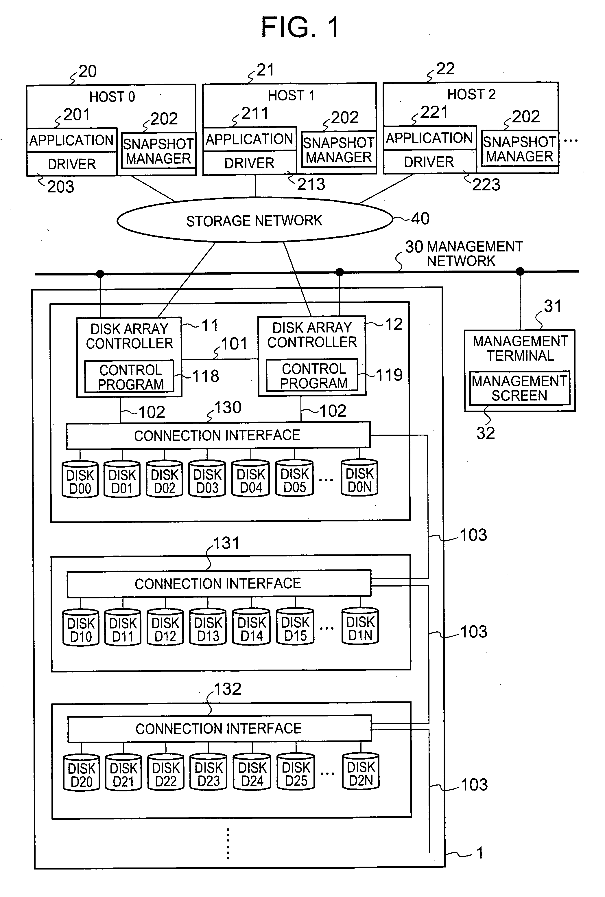
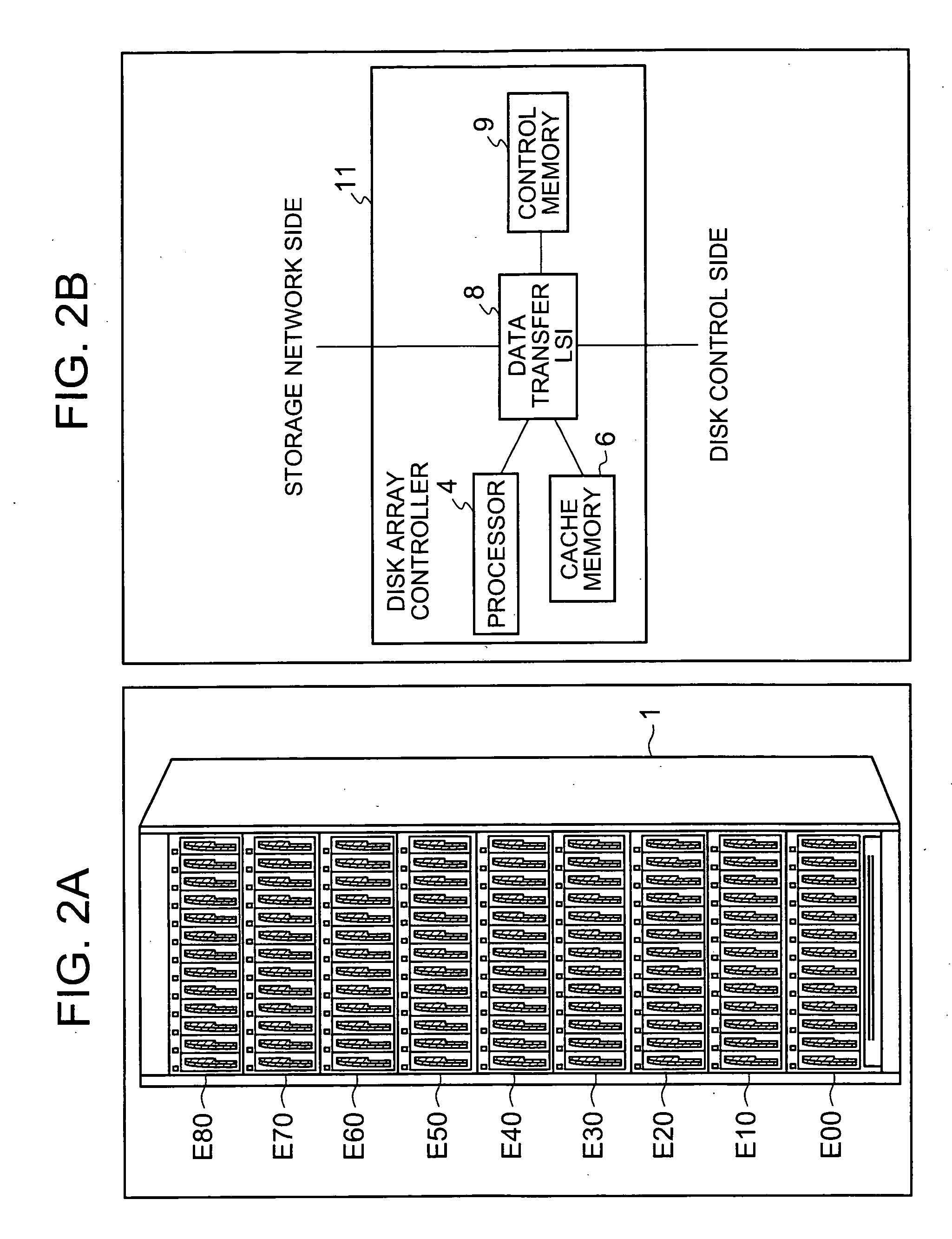
[0037]FIG. 1 is an explanatory drawing illustrating a schematic configuration example of a disk array device employing the storage system of the embodiment of the present invention. FIG. 2A illustrates an example of an external view of the display device shown in FIG. 1. FIG. 2B is a configuration example of the disk array controller.

[0038] The disk array device 1 comprises disk array controllers 11, 12, connection interfaces 130, 131, 132, and a plurality of disk storage devices (referred to hereinbelow as disk devices) D00-D2N. For example, as shown in FIG. 2A, the plurality of disk devices D00-D2N are installed in respective disk housings E00-E80 of the disk array device 1 and constitute a RAID group corresponding to the prescribed RAID level.

[0039] The disk array controllers 11, 12 are control circuits capable of executing control of various types in...


PUM


Abstract

Data can be recovered at the point in time when the consistency is provided, without increasing a load on the host.
The control program 118 updates the snapshot generation at the point in time when the snapshot is taken for each occurrence of the point in time when the snapshot is taken. In cases where new data are written into PVOL1 from the point in time when the snapshot has been taken until the next point in time when the snapshot is taken, the old data are saved by the CoW in DVOL1 and new data are written into PVOL1. Each time new data are written into PVOL1, the update differential data, which are the copy of this data, are prepared and written into DVOL1. The opportunity of providing the consistency of PVOL1, which occurs independently of the operations of the user of the host computer 20, is taken and the update differential generation, which is the generation of update differential data at each point in time where the update differential data has been set, is updated each time the opportunity is taken. The recovery of PVOL1 is conducted based on the managed update differential generation and snapshot generation.

Description

CROSS-REFERENCE TO PRIOR APPLICATION [0001] This application relates to and claims priority from Japanese Patent Application No. 2005-295025, filed on Oct. 7, 2005 the entire disclosure of which is incorporated herein by reference. BACKGROUND OF THE INVENTION [0002] 1. Field of the Invention [0003] The present invention relates to storage control technology, and more particularly to backup and recovery. [0004] 2. Description of the Related Art [0005] Disk array devices comprising a plurality of arranged disk storage devices (for example, hard disk drives) are known. Two or more logical volumes are prepared in a plurality of disk storage devices. A disk array device receives a command sent from a host computer, and following this command, writes data received from the host computer or reads data from logical volumes and transmits the data to the host computer. [0006] A RAID (Redundant Array of Independent Disks) technology is generally employed in disk array devices. Furthermore, sev...

Claims


Application Information

Patent Timeline
Patent Type & Authority Applications(United States)
IPC IPC(8): G06F17/30
CPCG06F11/1435G06F2201/84
Inventor ARAI, MASAHIROMATSUNAMI, NAOTO
Owner HITACHI LTD
Why Eureka
Try Eureka