Machine tool with workpiece measuring instrument and operating method for the same

a technology machine tool, which is applied in the direction of mechanical measuring arrangement, manufacturing tools, instruments, etc., can solve the problems of workpiece measuring instrument hot and defective, degraded function, and inability to accurately measure, so as to improve durability and simplify the effect of position switching means and precise measurements

Inactive Publication Date: 2007-04-19
MURATA MASCH LTD
View PDF8 Cites 19 Cited by
  • Summary
  • Abstract
  • Description
  • Claims
  • Application Information

AI Technical Summary

Benefits of technology

[0006] With this configuration, the workpiece measuring instrument is located inside the machining area while the workpiece is not being machined, and the workpiece is thus measured near the machining position. During workpiece machining, the workpiece measuring instrument can be retracted to the storage position outside the machining area so as not to be affected by chips or cutting heat. This enables the workpiece measuring instrument to be always kept in appropriate conditions to achieve precise measurements, and the durability of the workpiece measuring instrument is also improved.
[0007] According to the present invention, preferably, the workpiece supporting means is movable in a lateral direction, and the workpiece measuring instrument is movable forward and backward so as to freely switch its position. Thus, the workpiece supporting means preferably moves in the lateral direction with respect to the workpiece measuring instrument moved forward, to measure the workpiece. With this configuration, the workpiece measuring instrument can move between a workpiece measuring position inside the machining area and the storage position outside the machining area through simple forward and backward movement, and the position switching means can thus be simplified. Where this configuration is applied to a machine tool such as a spindle-movable lathe which has workpiece supporting means moving in the lateral direction, no new mechanism is required for moving the workpiece supporting means in the lateral direction.
[0008] In the present invention, an entrance may be provided in the bed so that the workpiece measuring instrument can move into and out of the bed, and a space portion existing inside the bed can thus be used as the storage position for the workpiece measuring instrument. The interior of the bed is not substantially affected by the cutting heat or heat from any other heat source and is isolated from external atmospheres; it is in a stable, appropriate environment. Thus, when the space portion existing inside the bed is used as the storage position for the workpiece measuring instrument, the workpiece measuring instrument can be kept in more appropriate conditions.

Problems solved by technology

Machining vibration may also propagate to the workpiece measuring instruments, which may thus fail.
The workpiece measuring instruments located near the machining position are also likely to be affected by cutting heat, and the workpiece measuring instruments may become hot and defective or have their functions degraded.

Method used


Image

  • Machine tool with workpiece measuring instrument and operating method for the same
  • Machine tool with workpiece measuring instrument and operating method for the same
  • Machine tool with workpiece measuring instrument and operating method for the same

Examples


Embodiment Construction

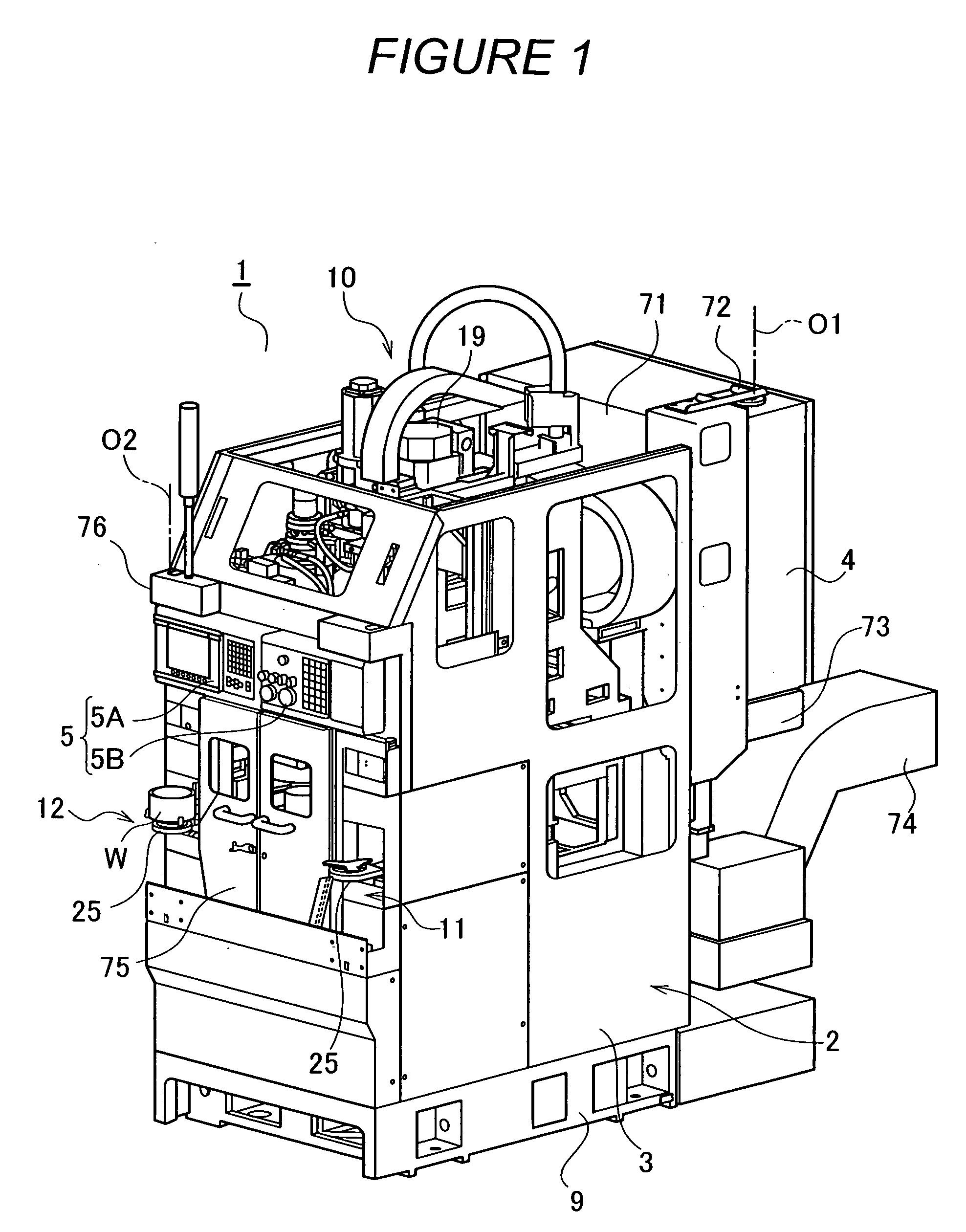
[0016] An embodiment of the present invention will be described with reference to the drawings. A machine tool according to the present embodiment is a vertical spindle-movable lathe including a control panel and an operation panel. In FIG. 1, a lathe 1, which is the machine tool according to the present embodiment, comprises a machine tool main body 2 including a generally rectangular-parallelepiped frame cover 3 having a vertically long rectangular front portion, a control panel 4 arranged on a rear surface of the machine tool main body 2, and an operation panel 5 arranged on a front portion of the machine tool main body 2.

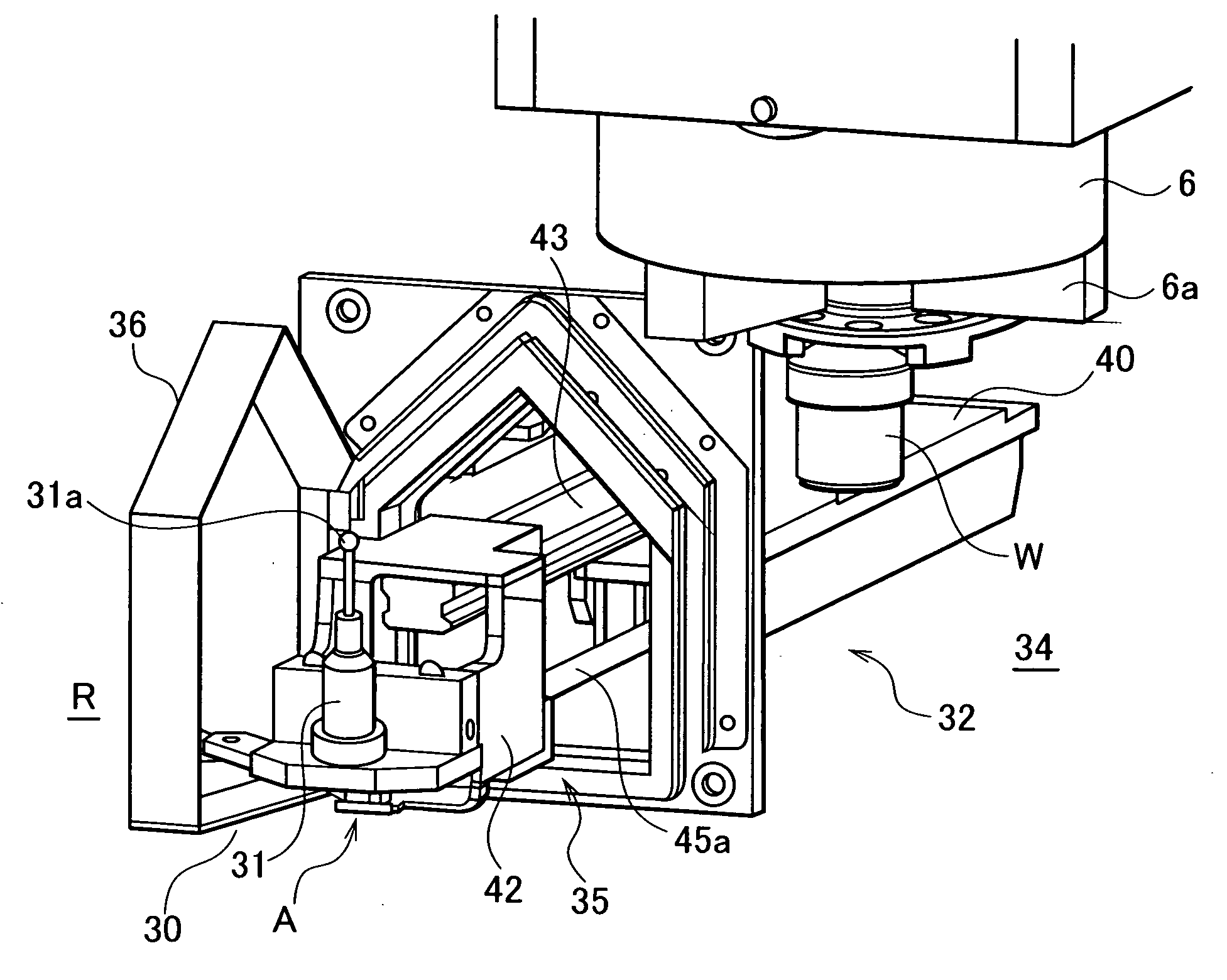
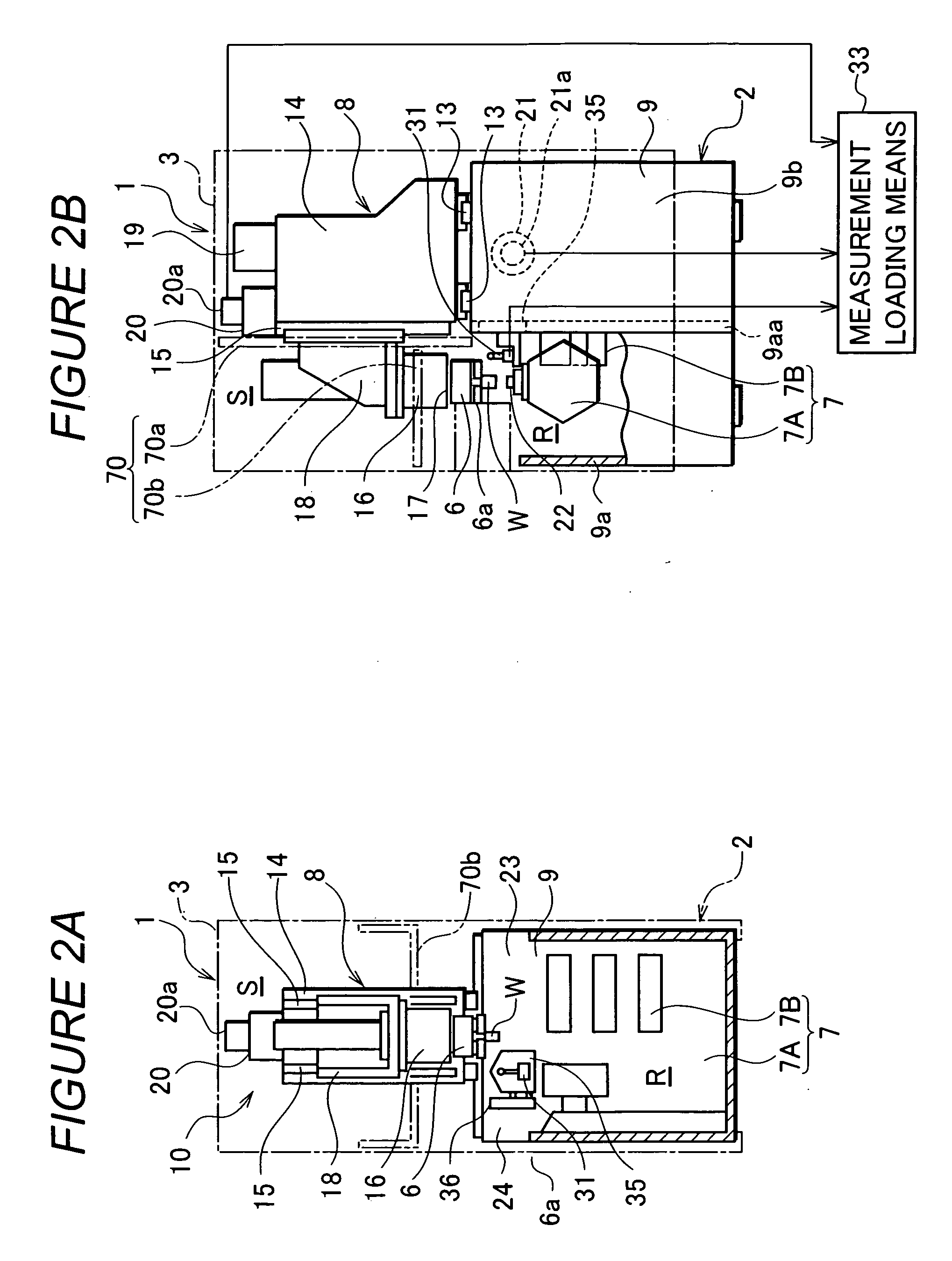
[0017] As shown in FIG. 2, the machines tool main body 2 comprises a spindle chuck 6 serving as workpiece supporting means to support a workpiece W downward, a machining means 7 provided in a machining area R to cut the workpiece W supported by the spindle chuck 6, a spindle moving means 8 for moving the spindle chuck 6 in a vertical and lateral directions, a w...


PUM


Abstract

The present invention provides a machine tool with a workpiece measuring instrument which prevents the workpiece measuring instrument from being affected by chips or cutting heat during non-machining, while enabling a workpiece W to be measured near a machining position. A machine tool has a bed 9 and a cover 3 surrounding a machining area R. Workpiece supporting means 6, machining means 7, and workpiece measuring instrument 31 are provided in the machining area R. Position switching means 32 is provided which moves the workpiece measuring instrument 31 between a position inside the machining area R and a storage position B outside the machining area R. The workpiece supporting means 6 is movable in a lateral direction. The workpiece measuring instrument 31 is movable forward and backward so as to freely switch its position, and measures the workpiece W.

Description

FIELD OF THE INVENTION [0001] The present invention relates to a machine tool with a workpiece measuring instrument that measures the dimensions of a machined workpiece, and the present invention also relates to an operating method for a machine tool with a workpiece measuring instrument. BACKGROUND OF THE INVENTION [0002] To improve machining precision, automatic control machine tools use a workpiece measuring instrument to measure the dimensions of a roughly machined workpiece to correct the amount by which a tool is fed during finish machining on the basis of measurements. For example, the Unexamined Japanese Patent Application Publication (Tokkai) 2004-34187 describes an example in which the machine tool is a lathe having, instead of tools, workpiece measuring instruments mounted on some of a plurality of tool stations of a tool stand comprising a turret. [0003] In the Unexamined Japanese Patent Application Publication (Tokkai) 2004-34187, the workpiece measuring instruments are...

Claims


Application Information

Patent Timeline
Patent Type & Authority Applications(United States)
IPC IPC(8): G01B5/20
CPCB23Q11/08B23Q11/0891B23Q17/20B23Q15/04B23Q15/18
Inventor KAWAI, HIROSHI
Owner MURATA MASCH LTD
Why Eureka
Try Eureka