

Miter saw having cut angle display device
a display device and miter saw technology, applied in the field of miter saws, can solve the problems of erroneous cutting angle learning from the table, and achieve the effect of convenient display
- Summary
- Abstract
- Description
- Claims
- Application Information
AI Technical Summary
Benefits of technology
Problems solved by technology
Method used
Image

Examples
first embodiment
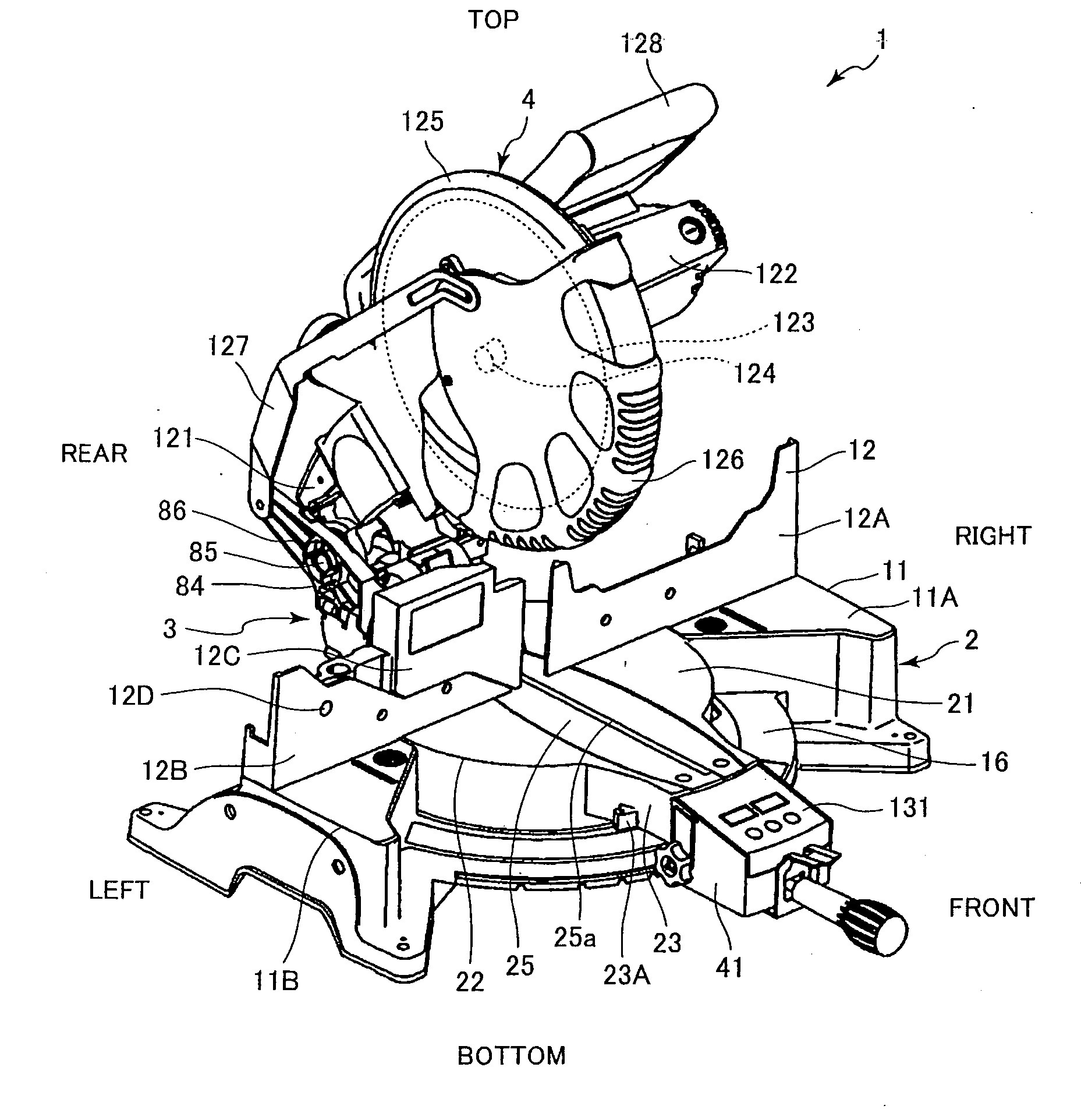
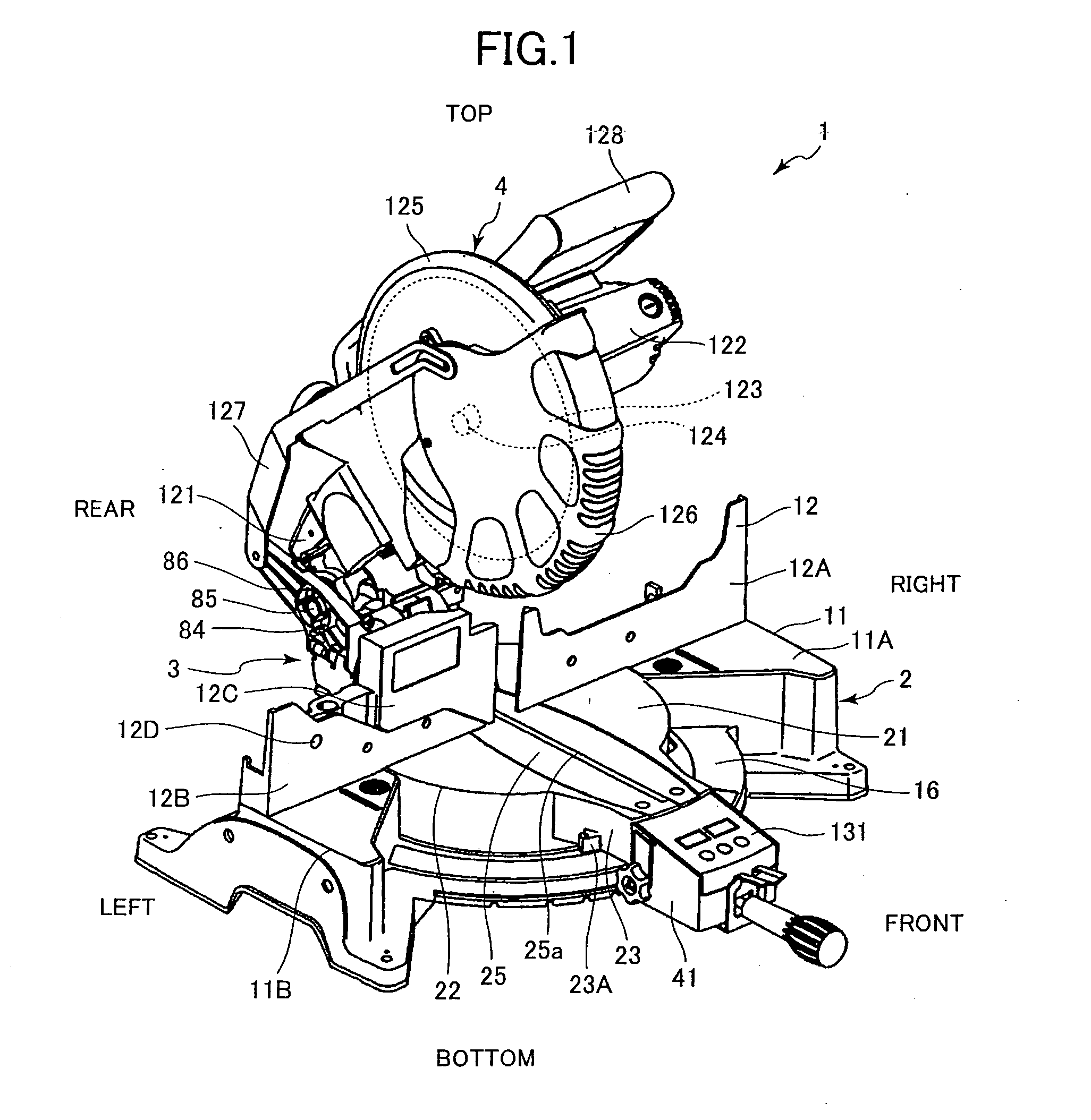
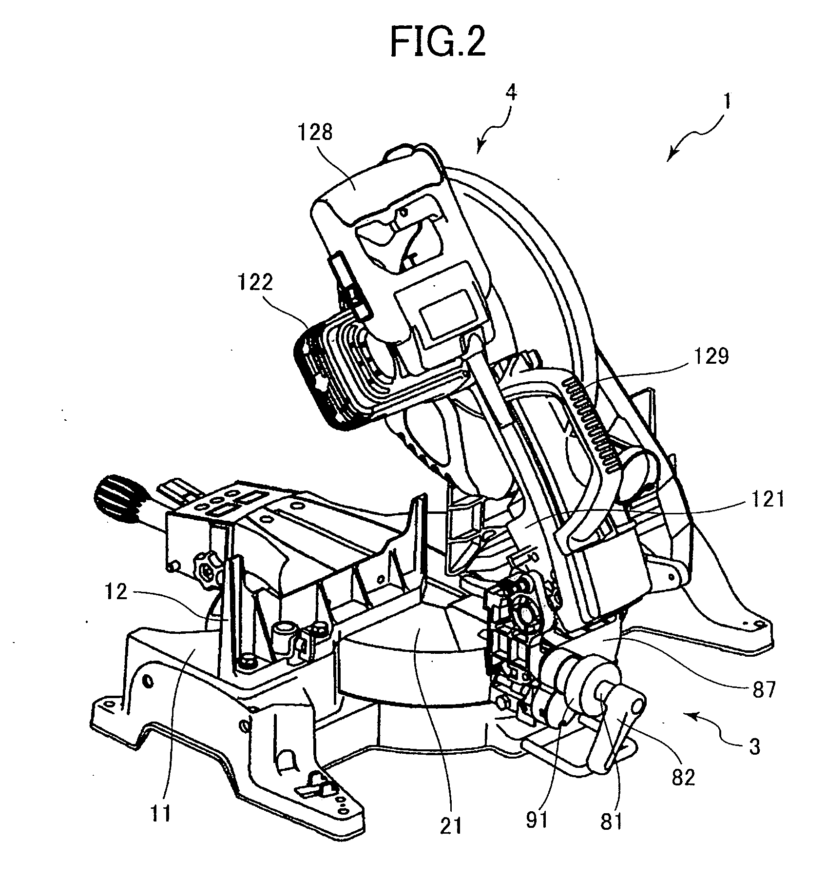
[0034] A miter saw according to the present invention will be described with reference to FIGS. 1 through 18. As shown in FIG. 1, the miter saw 1 includes a base section 2 installed on a stand or a floor for mounting thereon a construction member as a workpiece such as a moulding member, a circular-saw unit 4 that cuts the workpiece, and a support section 3 supporting the circular saw unit 4 pivotally movably toward and away from the base section 2 and laterally tiltably relative to the base section 2.
[0035] The base section 2 includes a base 11 serving as a ground section, a turntable 21 and a fence 12. The turntable 21 is supported on the base 11 and is rotatable about its axis with respect to the base 11. The turntable 21 cooperates with the base 11 to support the workpiece. The fence 12 laterally extends over the base 11 and is supported on the base 11. The fence 12 has an abutment surface extending in the lateral direction and facing frontward in contact with a side surface of ...
second embodiment
[0088] A miter saw according to the present invention will next be described with reference to FIGS. 20 to 22. A cutting angle display device 201 for use in a miter saw performs prompt computation and display of the cutting angle when cutting with the miter saw the construction member 194 (member 195 to be installed on the first wall 191 and the ceiling 193 and member 196 to be installed on the second wall 192 and the ceiling 193 as shown in FIG. 16) such as a moulding member to provide splicing ends. The cutting angle display device 201 can be assembled by means of a jig such as a belt (not shown) into an ordinary miter saw equipped with the tilt mechanism for tilting the circular saw unit, and angularly moving mechanism for angularly rotating the circular saw unit.
[0089] The cutting angle display device 201 has a surface provided with a digital display 202 for displaying a cutting angle, an angle input switch A 203 for inputting an angle of tens digit, an angle input switch B 204 ...
PUM
| Property | Measurement | Unit |
|---|---|---|
| Angle | aaaaa | aaaaa |
Abstract
Description
Claims
Application Information