Kinetic energy rod warhead with aiming mechanism

a technology of kinetic energy rods and warheads, which is applied in the direction of weapons, ammunition projectiles, projectiles, etc., can solve the problems of not being able to navigate, not always effective at destroying targets, and heavy casualties, so as to improve the chance of destroying targets and improve aiming accuracy

Inactive Publication Date: 2007-04-19
RAYTHEON CO
View PDF99 Cites 21 Cited by
  • Summary
  • Abstract
  • Description
  • Claims
  • Application Information

AI Technical Summary

Benefits of technology

[0013] It is a further object of this invention to provide a kinetic energy rod warhead which has a better chance of destroying a target.
[0014] It is a further object of this invention to provide a kinetic energy rod warhead with improved aiming accuracy.
[0015] The subject invention results from the realization that a kinetic energy rod warhead with enhanced aiming resolution can be achieved with explosive charge segments deployed in timed combinations to drive the rods in a specific deployment direction to more accurately strike a target.
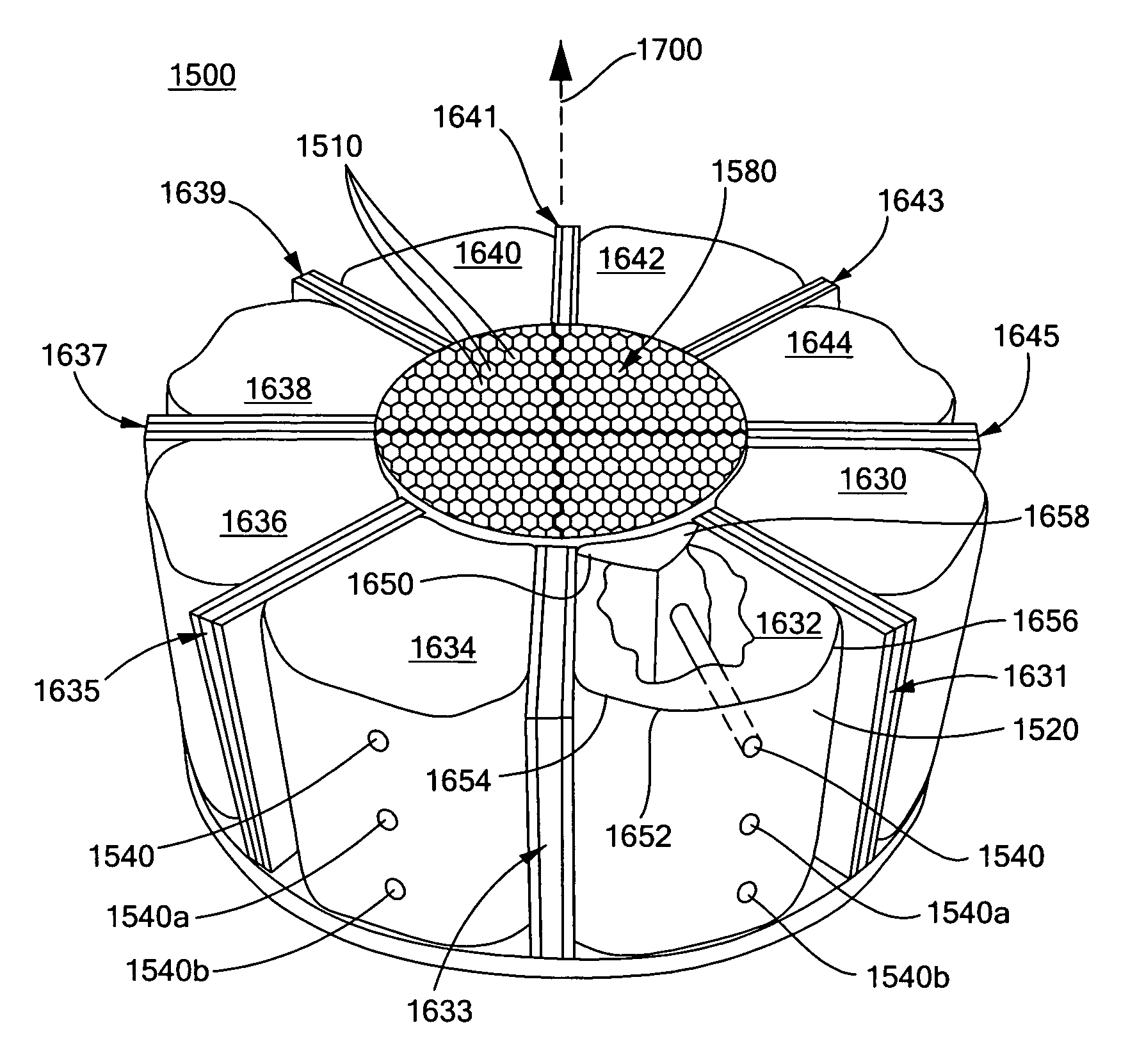
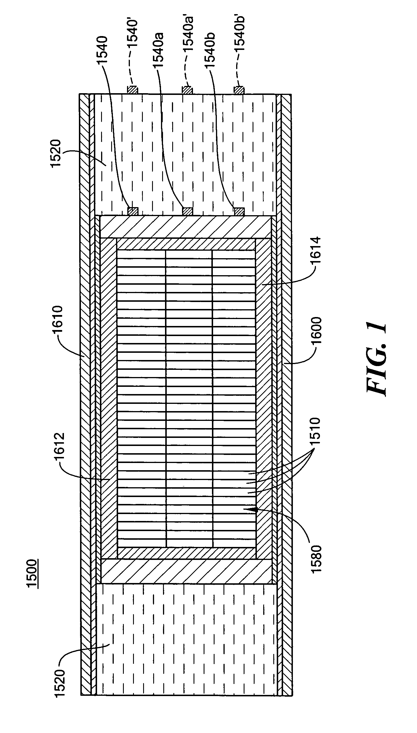
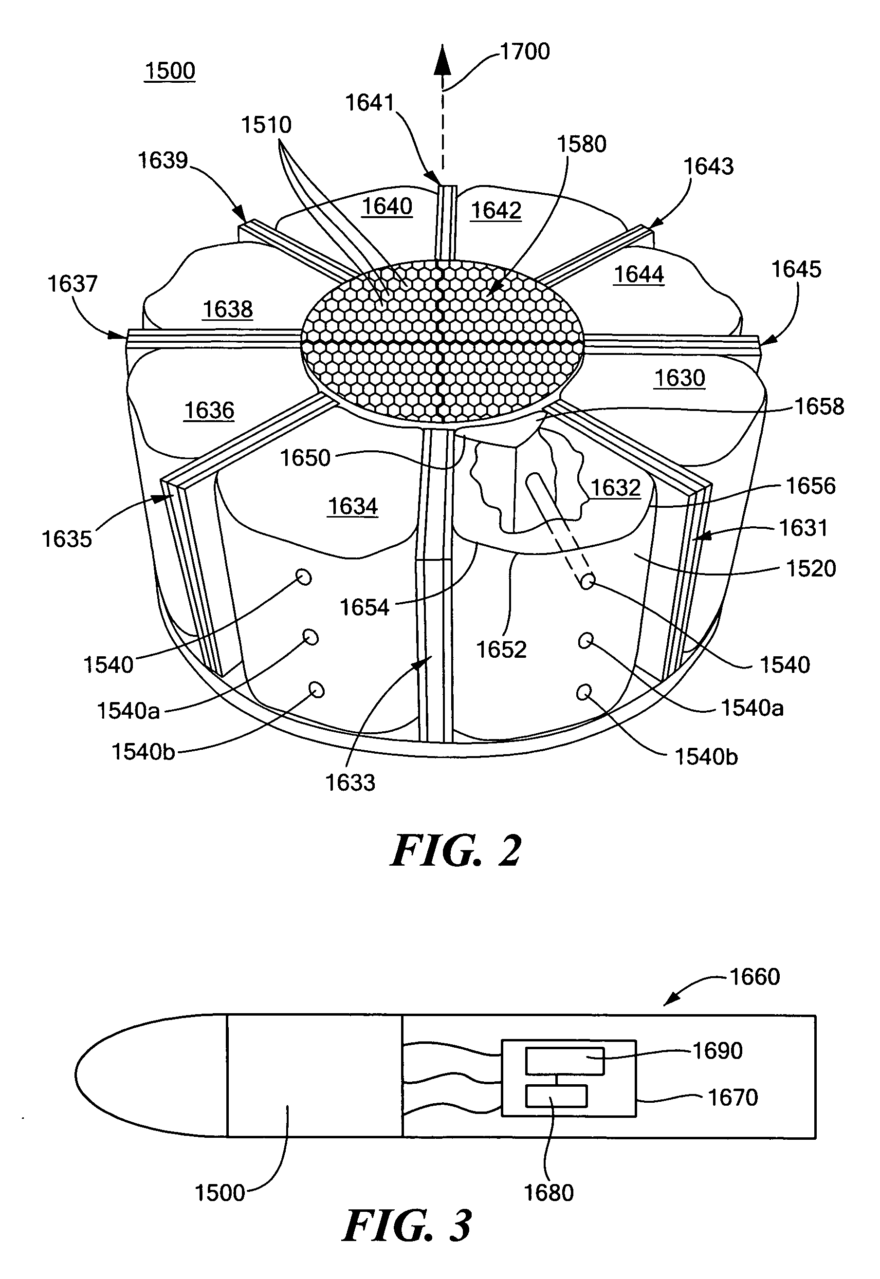
[0018] This invention features an aimable kinetic energy rod warhead system including a plurality of rods, explosive segments disposed about the plurality of rods, and at least one detonator for each explosive segment. A target locator system is configured to locate a target relative to the explosive segments and a controller is responsive to the target locator system. The controller is configured to selectively detonate specified explosive segments at different times dependent on the desired deployment direction of the rods to improve aiming resolution of the warhead. The selective detonation of specified explosive segments generates deployment vectors. The sum of the deployment vectors is a resolved deployment vector in the desired deployment direction. The warhead system may include eight explosive segments and there may be one detonator for each explosive segment. The warhead system may include sympathetic shields between each explosive segment, and the shields may be made of a composite material, which may be steel sandwiched between polycarbonate resin sheet layers. The rods may be lengthy metallic members and may be made of tungsten, and the rods may have a cylindrical cross-section. The explosive segments may be wedge-shaped and the explosive segments may surround the plurality of rods.
[0022] This invention also features a method of improving the aiming resolution of a kinetic energy rod warhead, the method including disposing explosive segments about a plurality of rods, locating a target relative to the explosive segments, and selectively detonating specified explosive segments at different times dependent on the desired deployment direction of the rods to improve aiming resolution. The method may further include disposing one detonator in each explosive segment. There may be eight explosive segments, and the method may further include disposing a sympathetic shield between the explosive segments. The shields may be made of a composite material which may be steel sandwiched between polycarbonate resin sheet layers. The rods may be lengthy metallic members and may be made of tungsten. The rods may have a cylindrical cross-section. The explosive segments may be wedge-shaped.

Problems solved by technology

Moreover, biological warfare bomblets and chemical warfare submunition payloads are carried by some “hit-to-kill” threats and one or more of these bomblets or chemical submunition payloads can survive and cause heavy casualties even if the “hit-to-kill” vehicle accurately strikes the target.
Blast fragmentation type warheads, unlike “hit-to-kill” vehicles, are not navigable.
The fragments, however, are not always effective at destroying the target and, again, biological bomblets and / or chemical submunition payloads survive and cause heavy casualties.
While a kinetic energy warhead including the foregoing design may be highly effective, the exact position of the target in relation to the warhead explosive charge segments may affect aiming accuracy.
The target may be positioned relative to the warhead such that the center of the rod set does not travel close to the target direction, resulting in aiming errors.
Additionally, the number of explosive segments detonated will affect the total spray pattern diameter, which may be critical in some applications.

Method used


Image

  • Kinetic energy rod warhead with aiming mechanism
  • Kinetic energy rod warhead with aiming mechanism
  • Kinetic energy rod warhead with aiming mechanism

Examples


Embodiment Construction

[0034] Aside from the preferred embodiment or embodiments disclosed below, this invention is capable of other embodiments and of being practiced or being carried out in various ways. Thus, it is to be understood that the invention is not limited in its application to the details of construction and the arrangements of components set forth in the following description or illustrated in the drawings. If only one embodiment is described herein, the claims hereof are not to be limited to that embodiment. Moreover, the claims hereof are not to be read restrictively unless there is clear and convincing evidence manifesting a certain exclusion, restriction, or disclaimer.

[0035] Current kinetic energy rod warhead designs allow a plurality of rods to be aimed, but the hardware can impose some constraints on the aiming accuracy. The present invention provides improved aiming resolution and better aiming accuracy despite such physical constraints.

[0036] The aimable kinetic energy rod warhead...


PUM


Abstract

An aimable kinetic energy rod warhead system includes a plurality of rods and explosive segments disposed about the plurality of rods. There is at least one detonator for each explosive segment. A target locator system is configured to locate a target relative to the explosive segments. A controller is responsive to the target locator system and is configured to selectively detonate specified explosive segments at different times dependent on the desired deployment direction of the rods to improve the aiming resolution of the warhead.

Description

RELATED APPLICATIONS [0001] This application is a Continuation-in-Part of prior U.S. patent application Ser. No. 11 / 059,891 filed Feb. 17, 2005 and this application is a Continuation-in-Part of prior U.S. patent application Ser. No. 11 / 060,179 filed Feb. 17, 2005, and the latter applications are each a Continuation-in-Part application of prior U.S. patent application Ser. No. 10 / 924,104 filed Aug. 23, 2004 and a Continuation-in-Part application of prior U.S. patent application Ser. No. 10 / 938,355 filed Sep. 10, 2004, and each of these latter two applications are a Continuation-in-Part of prior U.S. patent application Ser. No. 10 / 456,777, filed Jun. 6, 2003 which is a Continuation-in-Part of prior U.S. patent application Ser. No. 09 / 938,022 filed Aug. 23, 2001, issued on Jul. 29, 2003 as U.S. Pat. No. 6,598,534B2. All of these patent applications and patents are incorporated herein by reference.FIELD OF THE INVENTION [0002] This subject invention relates to improvements in kinetic en...

Claims


Application Information

Patent Timeline
Patent Type & Authority Applications(United States)
IPC IPC(8): F42B12/22F42B12/00
CPCF42B12/06F42B12/60F42C19/095
Inventor LLOYD, RICHARD M.
Owner RAYTHEON CO
Why Eureka
Try Eureka